


CV-A50 / CV-A60
6.4. External Trigger Modes
This camera has 5 external asynchronous trigger modes, which can be set by RS-232C commands.
1. Edge Pre-select Mode.TR=1 Pre-selected exposure. (SM=0, SM=1)
2. Pulse Width Control Mode. TR=2 Pulse width controlled exposure.
3. Frame Delay read out mode. TR=3 PWC exposure read out by ext. VD.
4. Long Time Exposure Mode. TR=4 Exposure is interval between ext. VD.
5. Start/stop Mode. TR=5 Exposure start by trigger and stop by ext. VD
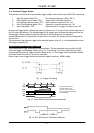
An external trigger pulse initiates the capture (input on pin 11 of the 12-pin Hirose connector or
pin 5 of the 6-pin Hirose). The leading edge of the trigger pulse initiates the exposure (this is a
falling edge if factory default) and the duration of the pulse governs the exposure
(accumulation) time. If the polarity of this pulse is reversed, the camera can be configured to
correct for it.
The duration of the external trigger pulse must be greater than 1H. It is recommended to make
this longer, typically 9H.
Important notes on using trigger modes:-
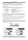
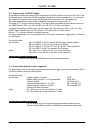
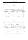
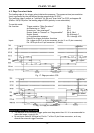
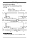
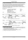
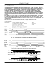
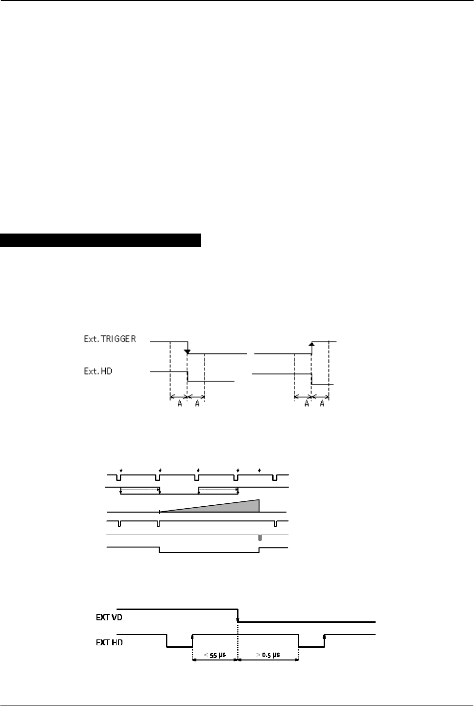
The accumulation is HD synchronously accumulation. The accumulation starts at the first HD
after the trigger leading edge. Shown in fig. 15. To avoid the <1H jitter caused by this delay,
synchronize the external trigger to HD as shown in fig. 14. The trigger level translations should
be placed inside the time A, which is 8 µseconds.
Do not input a new trigger before the previous video is read out. (WEN is high).
A
=
8µse
A=8
µ
sec
c
Fig. 14. Trigger/HD timing.
t
1
t
2
t
3
t
4
t
5
HD
Trigger
Xsub
Xsg
EEN
Accum
t
1
t
2
t
3
t
4
t
5
HD
Trigger
Xsub
Xsg
EEN
Accum
HD
Trigger
Xsub
Xsg
EEN
Accum
Note: Xsg and Xsub are
internal signals in the
camera. They are shown in
the timing diagram for better
understanding.
Fig. 15. Pulse Width H synchronous accumulation.
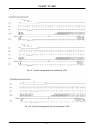
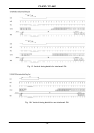
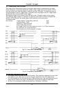
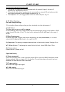
Fig. 16. Ext. HD and ext. VD phase conditions.
- 11 -