


CV-A50 / CV-A60
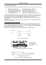
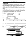
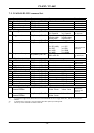
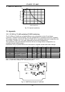
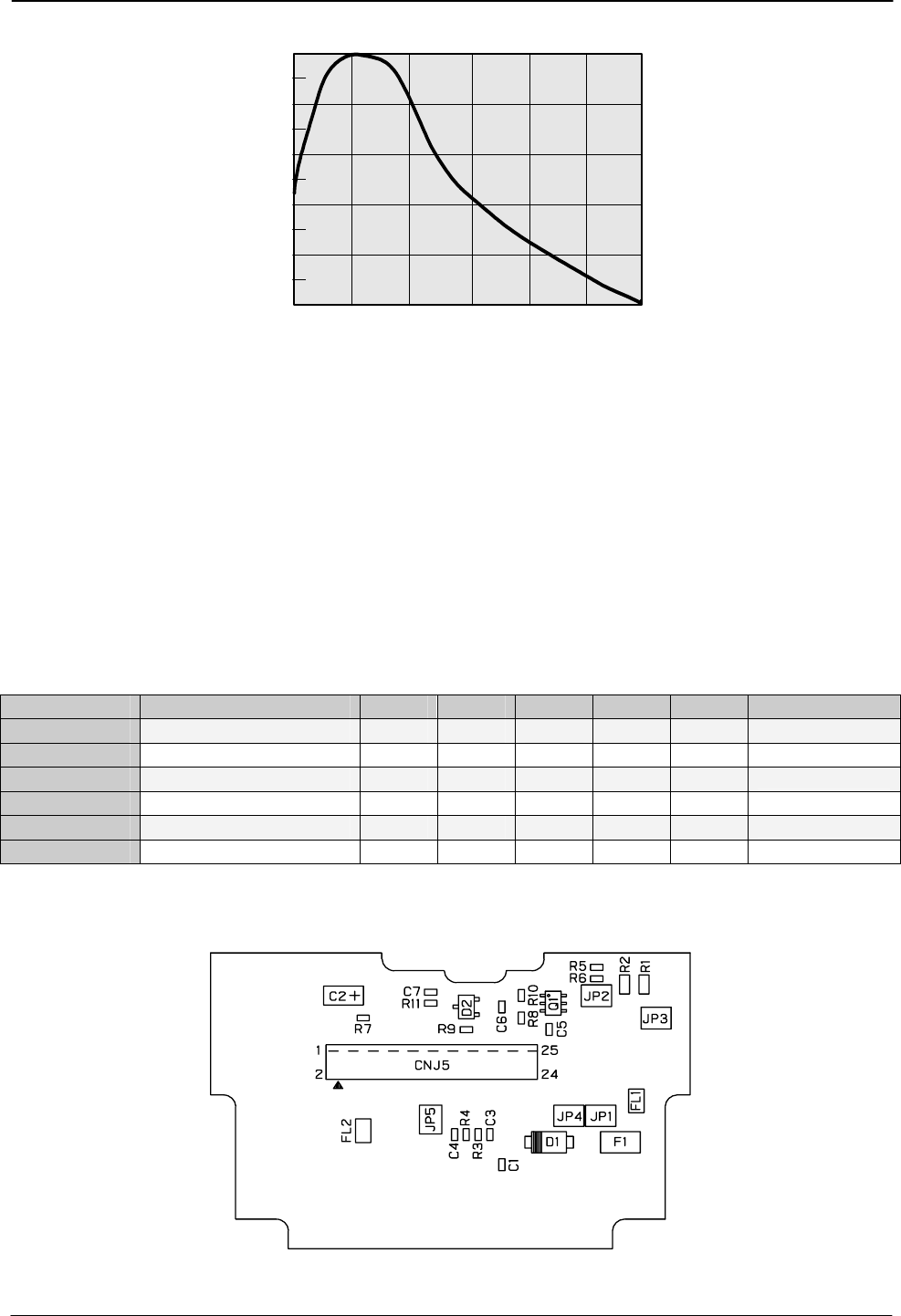
9. Spectral Sensitivity
400 500 600 700 800 900
Wave Length (nm)
1.0
0.8
0.6
0.4
0.2
0.0
Relative Response
1000
Fig. 30. Spectral sensitivity.
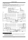
10. Appendix
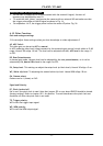
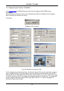
10.1. CV-A50 or CV-A60 emulating CV-M50 interfacing
The CV-A50 and CV-A60 have a slightly different pin configuration on the 12-pin Hirose
connector, compared to the M-series. This new configuration is compliant to the EIA-J standard.
This means, however, that the CV-A50 and CV-A60 are not completely backward compatible with
the CV-M50, CV-M300, etc in all cases (depending on the cable configuration).
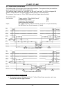
This application note gives detailed instruction on how to change the pin configuration, by
changing internal solder jumpers.
Please note: Only a qualified electronics technician or engineer should make these changes.
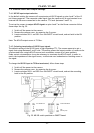
Hirose pin # Function JP2 JP3 JP5 JP1 JP4 Remarks
9 PCLK output enabled Short
Note 2
9 No connection Open
10 WEN output Open Short
10 Connected to ground Short Open
11 Ext Trigger input Open Short
11 +12V DC in Short Open
Note : Configuration shown in Bold+Italic is factory default setting
Note 2: The RS-232C command “PC” must be set to CLK
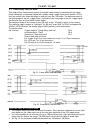
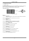
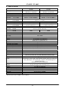
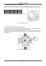
Fig. 31. PK8279 Rear Board of CV-A50/60
- 23 -