


CV-A50 / CV-A60
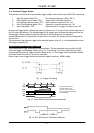
6.2. Input-output of HD/VD Signals
In the default setting the camera will accept external HD/VD signals on pin 6 and 7 of the 12 pin
Hirose connector. If external HD/VD is applied, the camera will synchronize to it. If no external
sync signals are applied, the camera will operate with its internal x-tal controlled sync.
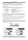
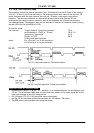
The time requirements to the relation between VD and HD are shown in fig. 16.
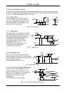
The input is TTL level as factory setting. It can be 75 Ohm terminated by the internal switch on
the PK8277 board. SW2-1 for HD and SW2-2 for VD. On for 75 Ohm termination.
To output the internal HD/VD signals on pin 6 and 7 the internal switch SW1-1 and 1-2 on the
PK8277 board should be set ON. The output is TTL level from a 75-Ohm source.
Refer to “7.4. Internal Switch and Jumper settings.”
In trigger modes there are no continuous VD out. Only after an external trigger pulse, a VD pulse
will be output.
To use this mode:
Set function: SW 1 on PK8277 to IN for external VD/HD input. Factory default.
SW 2 on PK8277 to 75 Ω for termination of VD/HD.
SW 2 on PK8277 to TTL for TTL level for VD/HD. Factory defaults.
SW 1 on PK8277 to OUT for internal VD/HD output.
Input: Ext. VD in or int. VD out on pin 7 on 12-pin connector.
Ext. HD in or int. HD out on pin 6 on 12-pin connector.
Important notes on using this mode
External sync system should follow the camera scanning system.
6.3. Continuous Operation (Non triggered)
For applications that do not require asynchronous external trigger (continuous operation). This is
the factory default setting of the camera.
To use this mode:
Set function: Trigger mode to “Normal” TR=0
Shutter mode “Normal” or “Programmable” SM=0, SM=1
“Shutter Speed” SH=0 through 7
“Programmable exposure” for CCIR PE=1 through 312
“Programmable exposure” for EIA PE=1 through 262
Polarity and other functions
Input: Ext. VD on pin 7 on 12-pin connector. If used.
Ext. HD on pin 6 on 12-pin connector. If used.
Important notes on using this mode
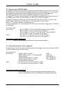
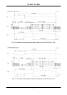
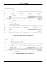
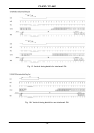
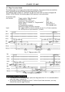
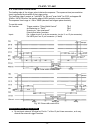
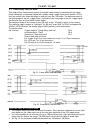
Fig. 10 through fig.13A on the following pages shows horizontal and
vertical timing details for CCIR and EIA interlaced and non-interlaced.
- 7 -