


CV-A50 / CV-A60
7.4. Internal Switch and Jumper Settings.
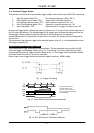
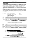
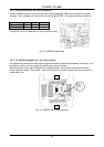
7.4.1 HD/VD input-output selection
In the default setting the camera will accept external HD/VD signals on pins 6 and 7 of the 12
pin Hirose connector. The composite video signal from the camera will be synchronized to an
external HD/VD source connected to the camera. TTL level (between 2 and 5 V).
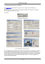
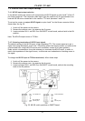
To set up the camera to output HD/VD signals on pins 6 and 7 on the Hirose connector follow
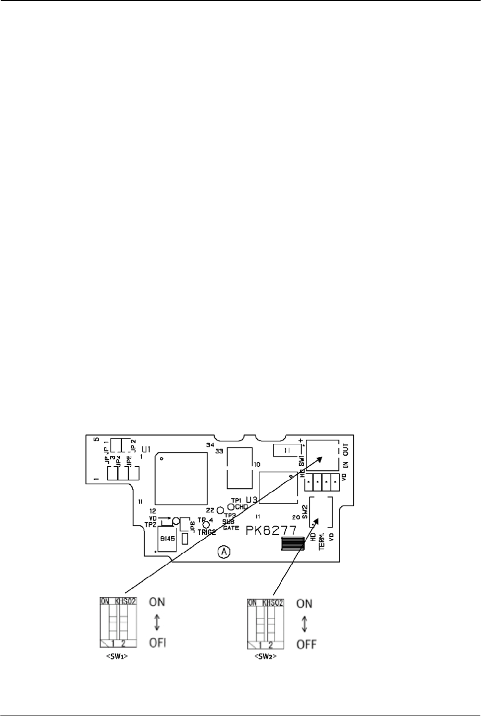
these steps. See fig. 29.
1. Switch off the power to the camera.
2. Remove the camera cover, by removing the 5 screws.
3. Locate switches SW1-1 and SW1-2 on the PK8277 circuit board, and set both in the ON
position.
Note: The HD/VD output source is 75 Ohm.
7.4.2. Selecting termination of HD/VD input signals
The default setting of the HD/VD input is high impedance TTL. The camera expects to get a
signal that swings between 2 and 5 volts. This setting allows the largest number of camera to be
synchronized from a single HD/VD source (such as another camera or a frame grabber).
Under certain circumstances it may be necessary to terminate the HD/VD input, in order to
match the impedance of the signal source, to eliminate over/undershoot or standing waves in
the signal.
To change the HD/VD input to 75Ohm terminated, follow these steps
1. Switch off the power to the camera.
2. Remove the camera cover, by removing the 6 screws.
3. Locate switches SW2-1 and SW2-2 on the PK8277 circuit board, and set the according
both in the ON position.
75
Ω
terminated
TTL
(factory set)
Int. HD/VD out
Ext. HD/VD in
(factory set)
Fig. 29. HD/VD switch positions on PK8277 board.
- 21 -