


CV-A50 / CV-A60
Important notes on using this mode:-
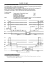
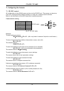
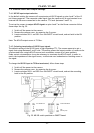
• As the start of exposure will be synchronized with the internal H signal, the start of
exposure may be shifted by max 1H.
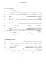
• To avoid this shift (jitter), synchronize the camera with an external HD and make sure that
the trigger pulse aligns to the HD signal as shown in Fig. 14.
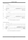
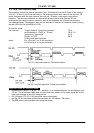
• For exposures <14 H, the trigger pulse is after the extern VD pulse. Fig. 26
6.10. Other Functions
Gain and analogue settings.
!! Do not adjust these settings unless you have knowledge to video adjustments !!
AS, AGC Switch
The video gain can be set to AGC or manual.
In AGC mode the video level is kept constant by the automatic gain control circuit within a 12 dB
range. Normal 700 mVpp ±30 mV. The level can be adjusted with AG, AGC level in the range 0
to 255.
RP, Rear Potentiometer
In manual gain mode, the gain level can be adjusted by the rear potentiometer, or it can be
adjusted by GA, Manual Gain level in the range 0 to 255.
SU, Setup level. This setting can adjust the setup level (or black level). Normal 20 mVpp ±2 mv.
WC, White clip level. To adjusting the wanted white clip level. Normal 800 mVpp ±30 mv.
GA, Gamma select.
Gamma can be 1 (linear) or 0.45.
Signal and Polarity.
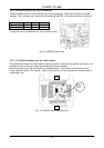
PC, Pixel clock on/off.
Set to on if the pixel clock is used. Note that jumper JP2 on rear board PK8274 should be closed.
(factory setting). Refer to chapter 10.2. for position. To avoid interference the pixel clock out
should be off when the pixel clock is not used.
TP, Trigger polarity.
Will invert the trigger-input signal.
WP, WEN polarity.
Will invert the WEN output signal.
- 17 -