


EN
ENEN
EN
&
&&
&
Master Page: Right
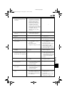
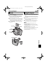
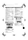
Controls
a Snapshot Button [SNAPSHOT]....... ੬
੬੬
੬ pg. 23, 42
b •Power Zoom Lever [T/W].................. ੬
੬੬
੬ pg. 18
•Speaker Volume Control
[VOL. +, –]........................................ ੬
੬੬
੬ pg. 20
c Power Switch [A, M, PLAY, OFF] ........ ੬
੬੬
੬ pg. 13
d Lock Button ......................................... ੬
੬੬
੬ pg. 13
e Diopter Adjustment Control................ ੬
੬੬
੬ pg. 12
f Recording Start/Stop Button................ ੬
੬੬
੬ pg. 17
g •Stop Button [8]................................. ੬
੬੬
੬ pg. 20
•Backlight Compensation Button
[BACK LIGHT]................................... ੬
੬੬
੬ pg. 47
h •Rewind Button [
3
].......................... ੬
੬੬
੬ pg. 20
•Focus Adjustment Button [FOCUS] ... ੬
੬੬
੬ pg. 45
i •Play/Pause Button [4/9].................. ੬
੬੬
੬ pg. 20
•Exposure Button [EXPOSURE] ........... ੬
੬੬
੬ pg. 46
j •Fast-Forward Button [
5
] .................੬
੬੬
੬ pg. 20
•Night-Alive Button [NIGHT].............. ੬
੬੬
੬ pg. 42
k Battery Release Button
[BATT.RELEASE] ................................... ੬
੬੬
੬ pg. 10
l VIDEO/MEMORY Switch
[VIDEO/MEMORY].............................. ੬
੬੬
੬ pg. 13
m Menu Button [MENU].......................... ੬
੬੬
੬ pg. 31
n •E-Mail Clip Recording Button
[E-MAIL]............................................ ੬
੬੬
੬ pg. 50
•Information Button [INFO]................ ੬
੬੬
੬ pg. 26
o Thumbnail Storing Button
[NAVI STORE]...................................... ੬
੬੬
੬ pg. 49
p •Index Button [INDEX] ....................... ੬
੬੬
੬ pg. 26
•Navigation Button [NAVI] ................. ੬
੬੬
੬ pg. 48
q •– Button............................................. ੬
੬੬
੬ pg. 31
•LCD Monitor Brightness Control
[MONITOR BRIGHT –]..................... ੬
੬੬
੬ pg. 13
r •+ Button ............................................ ੬
੬੬
੬ pg. 31
•LCD Monitor Brightness Control
[MONITOR BRIGHT +]..................... ੬
੬੬
੬ pg. 13
s •D.S.C. Playback Select Button
[SELECT].................................... ੬
੬੬
੬ pg. 24 – 29
•Set Button [SET]................................. ੬
੬੬
੬ pg. 31
t Cassette Open/Eject Switch
[OPEN/EJECT]...................................... ੬
੬੬
੬ pg. 15
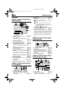
Connectors
The connectors are located beneath the covers.
U USB (Universal Serial Bus)
Connector............................................ ੬
੬੬
੬ pg. 66
V Digital Video Input/Output Connector [DV]
(i.Link*).................................... ੬
੬੬
੬ pg. 53, 54, 66
* i.Link refers to the IEEE1394-1995 industry
specification and extensions thereof. The logo
is used for products compliant with the i.Link
standard.
W S-Video/Audio/Video Input/Output and Edit
Connector [S/AV] .................... ੬
੬੬
੬ pg. 22, 52, 62
X DC Input Connector [DC] ............. ੬
੬੬
੬ pg. 10, 11
Indicators
C Power/Charge Lamp
[POWER/CHARGE]..................੬
੬੬
੬ pg. 10, 13, 17
D Tally Lamp................................੬
੬੬
੬ pg. 17, 37, 44
Other Parts
b Viewfinder............................................੬
੬੬
੬ pg. 12
c Shoulder Strap Eyelet .............................੬
੬੬
੬ pg. 7
d Battery Pack Mount..............................੬
੬੬
੬ pg. 10
e Grip Strap.............................................੬
੬੬
੬ pg. 12
f Speaker ................................................੬
੬੬
੬ pg. 20
g Stereo Microphone...............................੬
੬੬
੬ pg. 59
h •Remote Sensor ...................................੬
੬੬
੬ pg. 56
•Camera Sensor
Be careful not to cover this area, a sensor
necessary for shooting is built-in here.
i Flash Sensor
Be careful not to cover this area, as it cortains a
sensor required by the flash.
j Flash.....................................................੬
੬੬
੬ pg. 43
k LCD Monitor..................................੬
੬੬
੬ pg. 12, 18
l Card Cover [MEMORY CARD] ............੬
੬੬
੬ pg. 16
m Stud Hole
n Tripod Mounting Socket .......................੬
੬੬
੬ pg. 12
o Monitor Latch ......................................੬
੬੬
੬ pg. 12
p Cassette Holder Cover..........................੬
੬੬
੬ pg. 15
REFERENCES
GR-D200US.book Page 81 Friday, April 11, 2003 1:05 PM