


70
MENU SCREENS
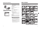
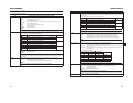
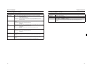
AUDIO/MIC Menu Screen
In VTR mode, the screen changes to the AUDIO menu screen.
*This is not displayed in VTR mode.
Item Function/Setting (bold characters indicate initial settings)
TEST TONE Sets whether to output a test audio signal (1kHz, –20dBFS or –12dBFS) during color bar output.
OFF :A test audio signal is not output.
ON : A test audio signal is output.
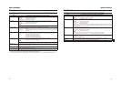
MIC WIND CUT* Selects whether to cut the lows (low frequency bands) from the audio input signal.
Use this when you want to reduce wind sounds from the microphone.
OFF : Low frequencies are not cut.
INPUT1 : Only cuts the low frequencies in the audio from the INPUT1 connector.
INPUT2 : Only cuts the low frequencies in the audio from the INPUT2 connector.
BOTH : Cuts the low frequencies in the audio from both the INPUT1 and INPUT2 terminals.
AUDIO REF.LEVEL Sets the reference audio level on the tape. (Both CH-1 and CH-2)
–20dB :Records with –20 dB as the reference audio level.
–12dB : Records with –12 dB as the reference audio level.
Set this if you are playing back the recorded tape on an ordinary DV device.
*Set this for both playback and recording.
*This is unrelated to the audio level via the IEEE1394 signal.
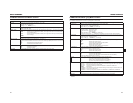
INPUT1 MIC REF.* Sets the reference audio input level for the INPUT1 connector.
–50dB :Sets the reference audio input level at –50 dB.
–60dB : Sets the reference audio input level at –60 dB.
INPUT2 MIC REF.* Sets the reference audio input level for the INPUT2 connector.
–50dB :Sets the reference audio input level at –50 dB.
–60dB : Sets the reference audio input level at –60 dB.
AUDIO MONITOR Selects whether stereo or mixed audio is output from the PHONES jack when the MONITOR SELECT switch is set
to BOTH.
STEREO : Stereo audio (CH-1 audio is output to L and CH-2 audio is output to R)
*Outputs only the CH-1 audio from the monitor speaker.
MIX :Mixed audio (CH-1 and CH-2 mixed audio is output to L and R)
AUDIO MODE* Selects the audio sampling frequency for recording. (Both CH-1 and CH-2)
(When HDV format is set, this is fixed at 48K and “[48K]” is displayed.)
32K : Digitally records with a 12-bit, 32 kHz sampling frequency.
48K :Digitally records with a 16-bit, 48 kHz sampling frequency.
* If the DV format is 12-bit, 32 kHz, up to 4 recording track channels are available.
Of those, this camcorder records on the CH-1 and CH-2 channels. This camcorder is not capable of dubbing.
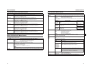
SEARCH AUDIO [DV] Selects whether to output audio when searching a tape recorded in DV format. (This also includes slow playback.)
ON :Audio is output.
OFF : Audio is not output.
PB AUDIO CH [DV] Selects which channel audio to output when playing back a DV tape with the audio signal recorded in 4 channels.
(Can only be set in VTR mode)
CH1/2 :Outputs the CH-1 and CH-2 channel audio.
This camcorder records the audio in CH-1 and CH-2 while shooting.
MIX : Outputs all 4 channels of audio at the same time.
CH3/4 : Outputs the CH-3 and CH-4 channel audio.
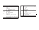
MEMO
This camcorder does not have a function for dubbing to the CH-3 and CH-4 channels.
PAGE BACK When the cursor is in this position, press the SHUTTER dial to return to the TOP MENU screen.
71
MENU SCREENS
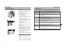
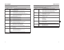
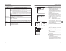
LCD/VF [1/3] Menu Screen
The LCD/VF menu screen consists of three screens. (1/3 screen, 2/3 screen, 3/3 screen)
The LCD/VF [1/3] menu screen can only be set in camera mode.
In VTR mode, this screen consists of two screens. (1/2 screen, 2/2 screen)
*1 SAFTY ZONE and CENTER MARK will not be displayed when the camcorder is in VTR mode (PLAY, STL, FWD, REV).
Item Function/Setting (bold characters indicate initial settings)
ZEBRA Switches the luminance level of the subject sections where the zebra pattern is displayed.
60-70% : Zebra pattern is displayed in sections with luminance levels between 60% and 70%.
70-80% :Zebra pattern is displayed in sections with luminance levels between 70% and 80%.
85-95% : Zebra pattern is displayed in sections with luminance levels between 85% and 95%.
OVER95% : Zebra pattern is displayed in sections with luminance levels over 95%.
OVER100% : Zebra pattern is displayed in sections with luminance levels over 100%.
F. NO/IRIS IND. Selects whether or not the F-number of the lens iris/iris level mark is displayed in the status display on the LCD mon-
itor or in the viewfinder. (STATUS 1 screen)
OFF :F-number and iris level mark is not displayed.
F.NO : F-number is displayed.
F.NO+IND. : F-number and iris level mark is displayed.
FILTER Selects whether or not the FILTER position of the unit is displayed in the status display on the LCD monitor or in the
viewfinder. (STATUS 1 screen)
OFF :FILTER position is not displayed.
ON : FILTER position is displayed.
SAFETY ZONE*1 Selects whether or not the safety zone is shown on the LCD monitor or in the viewfinder together with the form of
the safety zone indication.
OFF :Not displayed
4:3 : 4:3 zone is displayed.
14:9 : 14:9 zone is displayed.
16:9 : 16:9 zone is displayed.
16:9+4:3 : 16:9 zone and 4:3 zone are display mixed. (This cannot be selected when DV format is set.)
CENTER MARK*1 Sets whether or not a center mark is displayed when the safety zone is displayed.
ON :Center mark is displayed.
OFF : Center mark is not displayed.
MEMO
When the SAFETY ZONE item is set to OFF, “- - -” is indicated and this item cannot be selected.
FOCUS ASSIST Sets the display color for focusing when running the FOCUS ASSIST function.
BLUE :Displays the area of focus in blue.
RED : Displays the area of focus in red.
GREEN : Displays the area of focus in green.
NEXT PAGE When you display the LCD/VF [2/3] menu screen, move the cursor to this position and press the SHUTTER dial.
PAGE BACK When the cursor is in this position, press the SHUTTER dial to return to the TOP MENU screen.