


10
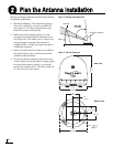
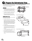
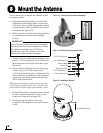
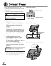
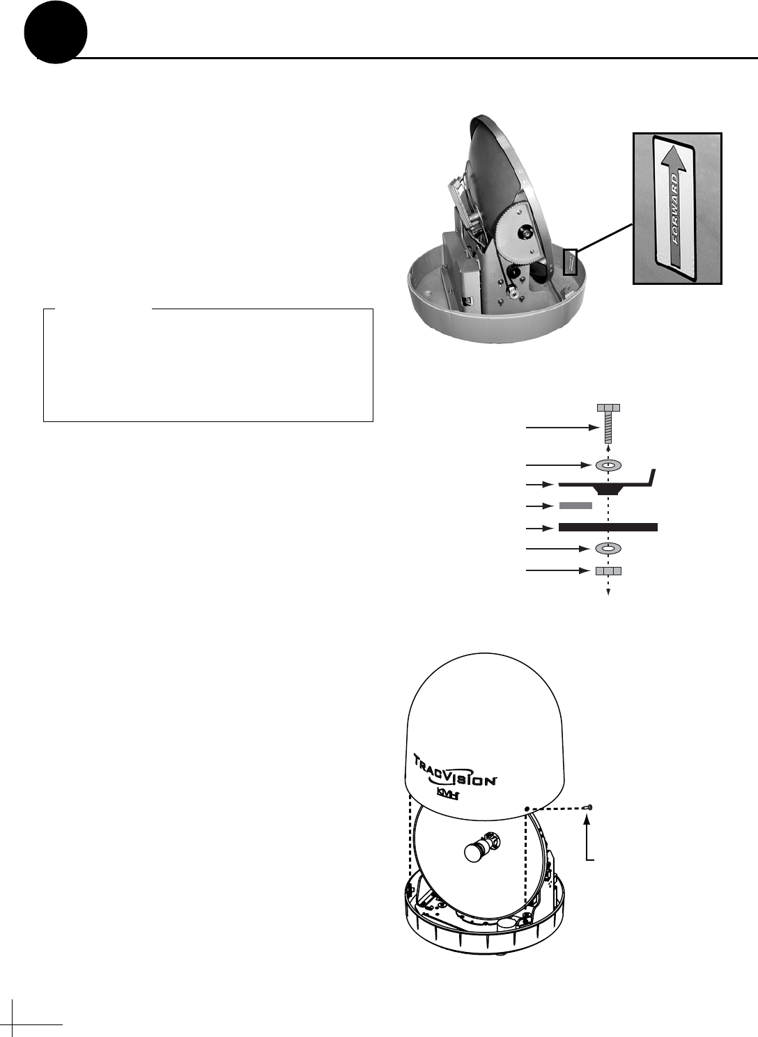
Follow these steps to mount the antenna to the
mounting surface.
a. Place the antenna baseplate over the holes
drilled in the mounting surface. Ensure the
“Forward” arrow inside the baseplate points
toward the bow and is parallel to the vessel’s
centerline (see Figure 18).
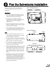
b. Make sure the four holes in the baseplate line
up with the four holes in the mounting
surface.
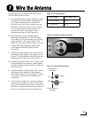
c. At each of the four baseplate mounting holes,
place a 1/4" flat washer on a 1/4"-20 bolt and
insert the bolt into the hole from above (see
Figure 19).
d. Secure each mounting bolt to the mounting
surface using a 1/4" flat washer and a
1/4"-20 lock nut from below. Tighten all four
bolts until the four rubber feet are bottomed
against the mounting surface and the foam
seal is fully compressed.
TIP: If you are installing a linear system, you may
wish to keep the radome off for now. Later, you will
need to adjust the skew angle of the antenna’s LNB.
e. Reinstall the radome onto the antenna. Secure
in place with the three #10-24 screws you
removed in Step 6a (see Figure 20).
f. Install a protective plastic screw cap
(supplied in the kitpack) over each radome
screw.
Figure 18: “Forward” Arrow in Antenna Baseplate
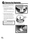
You will need to rotate the antenna assembly
by hand to see all four mounting holes. Rotate
the antenna assembly slowly. If it hits a
mechanical stop with excessive force, the
limit switch might become damaged.
IMPORTANT!
1/4"-20 x 3" Bolt (x4)
1/4" Flat Washer (x4)
Foam Seal
Mounting Surface
1/4" Flat Washer (x4)
1/4"-20 Lock Nut (x4)
Antenna Base
Figure 19: Mounting the Antenna (Side View)
Figure 20: Installing the Radome
#10-24 Screws (x3)
Mount the Antenna
8