


14
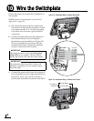
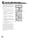
Follow these steps to connect power. The
switchplate supplies power to both the antenna
and the MCP.
a. Before you begin, disconnect vessel power.
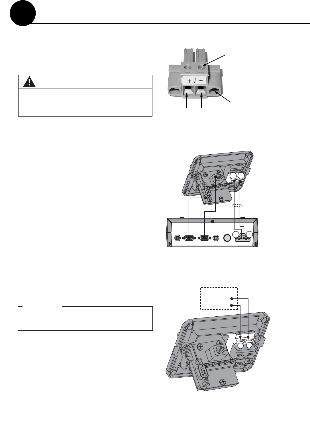
b. Route a set of power wires from the
switchplate’s power output terminals to the
MCP (for cable specifications, see Figure 2 on
page 3). Connect the wires to the plastic
power plug supplied in the kitpack (see
Figure 27).
NOTE: You should now have three wires
connected to each power output terminal on the
switchplate: one set of wires to power the antenna,
one set to power the MCP, and one set to power
the switchplate’s indicator lamp (installed at the
factory).
c. Tighten the terminal screws on the
switchplate to secure all wires in place.
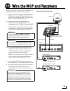
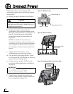
d. Plug the MCP power plug into the “Power
In” jack on the MCP (see Figure 28). Secure in
place with the retaining screws.
e. Connect a power cable to 12 VDC vessel
power (for cable specifications, see Figure 2
on page 2).
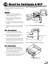
f. Connect your vessel power wires to the
power (+) and ground (-) input terminals on
the switchplate (see Figure 29).
CAUTION
For your own safety, disconnect vessel power
and make sure the circuit is dead before you
connect any power wires.
Figure 27: MCP Power Plug
Terminal Screw (x2)
GroundPower
Retaining Screw (x2)
HDTV
CONTROL
ANTENNA UNIT RF PORT TONE
DETECT
FUSE POWER IN
+ / –
Switchplate-to-MC
P
Power Cable
MCP
+
–
+
–
Figure 28: MCP Power Wiring
Power supplied to the antenna must not fall
below 11 VDC or exceed 16 VDC.
IMPORTANT!
11-16 VDC
Ground
Vessel Power
+
–
Figure 29: Switchplate Wiring - Vessel Power Cable
Connect Power
12