


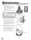

9
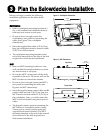
Follow these steps to connect the data, power,
and RF cables to the antenna.
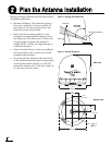
a. First determine the number of RF coax cables
required for your particular installation. If
you wish to connect just one satellite TV
receiver to the TracVision system, only one
RF cable is required. If you wish to connect
two or more receivers to the system, you
need two RF cables. (See Figure 15 to
determine the type of cable required.)
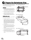
b. Route the data, power, and RF cables
belowdecks through the 3" (80 mm) cable
access hole. Leave an adequate service loop,
approximately 8" (20 cm) of slack, in the
cables for easy serviceability. Later, you will
connect the data and power cables to the
switchplate and the RF cable(s) to the
receiver(s).
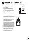
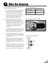
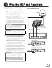
c. Connect the data cable to the “Data” jack on
the bottom of the antenna (see Figure 16 and
Figure 17). Hand-tighten until the connector
locks in place; do not use excessive force.
d. Connect the power cable to the “Power” jack
on the bottom of the antenna. Hand-tighten
until the connector locks in place; do not use
excessive force.
e. Connect an RF coax cable to the “RF1” jack on
the bottom of the antenna. Hand-tighten,
then tighten with a 7/16" wrench for 1/4 turn
to ensure an electrical and weather-proof
connection.
f. If you wish to connect two or more receivers,
connect a second RF coax cable to the “RF2”
jack on the bottom of the antenna. Label both
RF cables to match the antenna connectors so
that you can easily identify the cables later.
Figure 15: RF Cable Guidelines
Cable Length Use Cable Type
<= 75 ft (23 m) RG-6
> 75 ft (23 m) RG-11
Figure 16: Connectors on Bottom of Antenna
RF1
RF2
Data
Power
Single Receiver
Installation
Second Receiver
Installation
Figure 17: Antenna Cable Connections
Wire the Antenna
7