


5
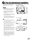
Before you begin, consider the following
installation guidelines for the belowdecks
equipment.
Switchplate
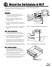
• Select a switchplate mounting location in a
dry, well-ventilated area belowdecks away
from any heat sources or salt spray.
• Be sure to leave enough room at the
switchplate’s rear panel for connecting the
cables (see Figure 5 for switchplate
dimensions).
• Since the supplied data cable is 50 ft (15 m)
long, the switchplate must be located within
50 ft (15 m) of the antenna.
• The switchplate mounting template at the
end of this manual shows the size of the hole
required for a flush-mount installation.
MCP
• Select an MCP mounting location in a dry,
well-ventilated area belowdecks away from
any heat sources or salt spray.
• Be sure the MCP’s front panel will be easily
accessible to the user. The owner will use the
MCP’s buttons to control the antenna.
• Be sure to leave enough room at the MCP’s
rear panel for connecting the cables (see
Figure 6 for MCP dimensions).
• Since the supplied main control cable and RF
control cable are both 25 ft (7.6 m) long, the
MCP must be located within 25 ft (7.6 m) of
the switchplate. Later, you will connect the
MCP to the switchplate using these special
cables.
• The kitpack contains parts for mounting the
MCP either to a horizontal surface (using
Velcro) or to a vertical surface (using the
supplied flush mount bracket). The MCP
mounting template at the end of this manual
shows the size of the hole required for a
flush-mount installation.
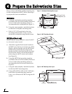
2.96"
(75.2 mm)
4.39"
(111.5 mm)
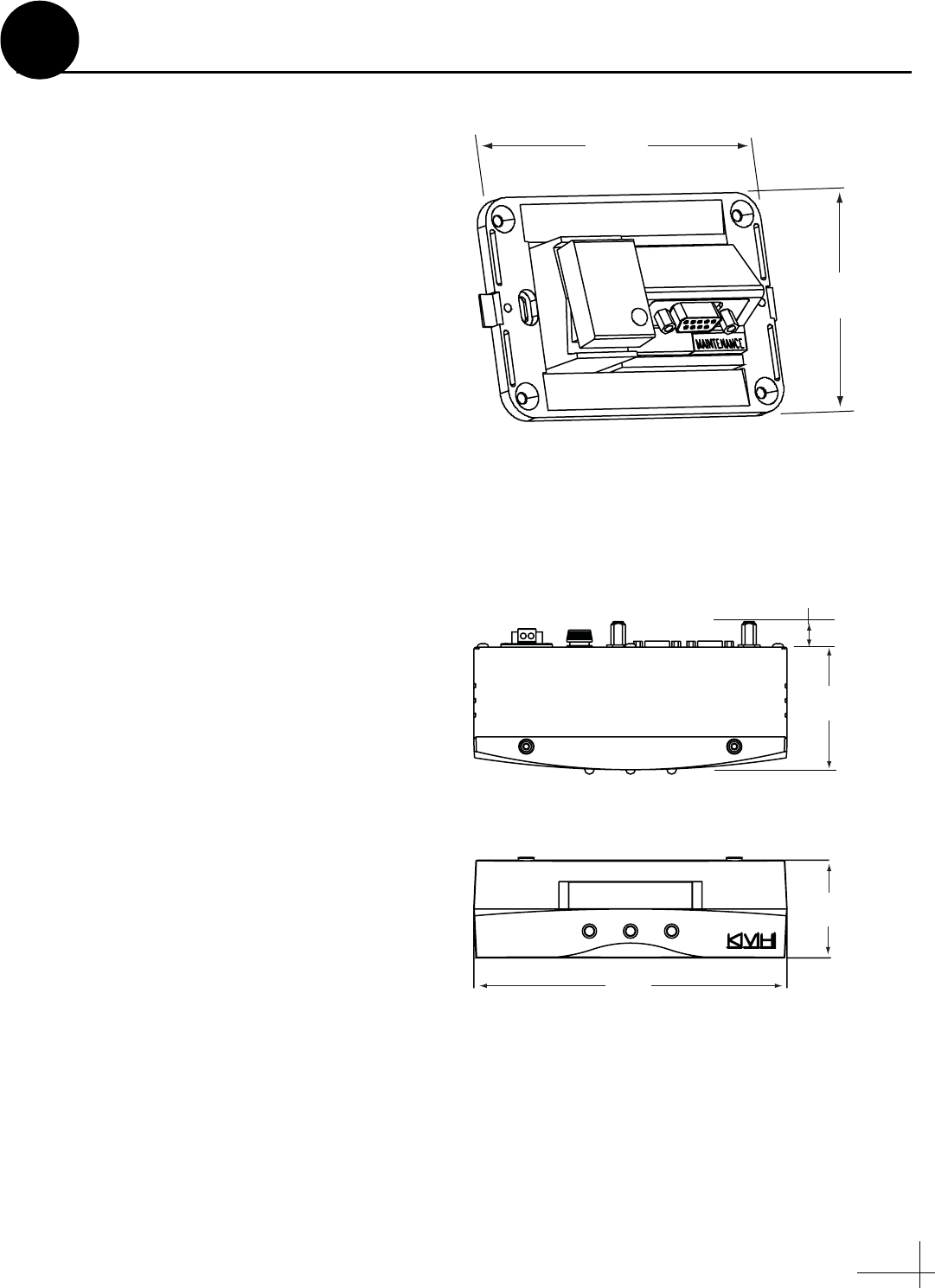
Figure 5: Switchplate Dimensions
8.1"
(205.7 mm)
3.17"
(80.6 mm)
0.66"
(16.7 mm)
2.52"
(64.1 mm)
Figure 6: MCP Dimensions
Front View
Top View
Plan the Belowdecks Installation
3