


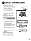
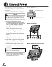
6
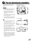
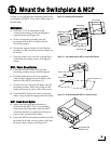
Once you have identified suitable mounting sites
for the switchplate and MCP, follow these steps
to prepare the sites for installation.
Switchplate
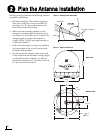
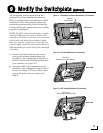
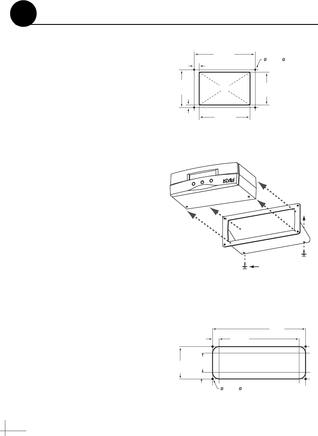
a. Using the switchplate mounting template
provided at the end of this manual, mark and
cut out a hole in the mounting surface to
accommodate the switchplate (see Figure 7).
b. Using the same template, mark the locations
for the four switchplate mounting holes.
c. Drill a 3/32" (2.25 mm) hole at the four
mounting hole locations. Later, you will
mount the switchplate using four #6 screws.
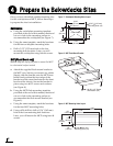
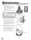
MCP (Flush Mount only)
NOTE: Skip this step if you plan to mount the MCP
to a horizontal surface instead.
a. Attach the supplied flush mount bracket to
the MCP now, before you connect any cables.
Simply slide the bracket onto the MCP from
behind and position the front edge of the
bracket over the seam line between the front
bezel and the chassis. Secure the bracket in
place using two #6-32 screws and washers
(see Figure 8).
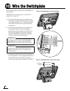
b. Using the MCP flush mounting template
provided at the end of this manual, mark and
cut out a hole in the mounting surface to
accommodate the flush mount bracket (see
Figure 9).
c. Using the same template, mark the locations
for the four MCP mounting holes.
d. Using a #29 drill bit, drill a 0.136" (3.45 mm)
hole at the four mounting hole locations.
Later, you will mount the MCP using four #8
screws.
3/32" ( 2.25 mm)
Mounting Hole (x4)
3.82"
(97 mm)
.32" (8 mm)
2.36"
(60 mm)
.16" (4 mm)
3.19"
(81 mm)
2.05"
(52 mm)
Panel Cutout
Figure 7: Switchplate Mounting Holes Layout
#6-32 x 1/2" Screw
and Washer (x2)
Figure 8: MCP Flush Mount Bracket
8.87"
(225 mm)
7.62"
(194 mm)
.63"
(16 mm)
3.08"
(78 mm)
1.83"
(46 mm)
.63"
(16 mm)
.136" ( 3.45 mm)
Mounting Hole (x4)
Figure 9: MCP Mounting Holes Layout
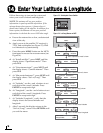
Prepare the Belowdecks Sites
4