


-12-
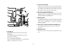
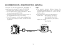
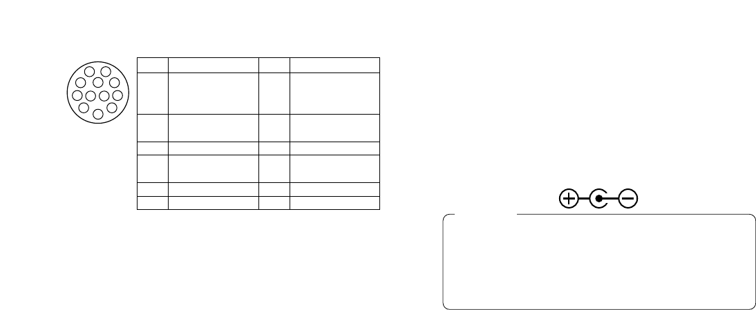
14. I/F Remote Connector (I/F REMOTE)
Input terminal dedicated to control signals from the
optional Remote Control Box (RCB) (such as the
WV-CB700A) and the RCU (such as the
WV-RC700A, WV-RC550) and the camera pan/tilt
unit (such as the AW-PH300A).
• WV-CB700A is connected through the optional
RCB cable (AW-CA50T10/AW-CA50B10).
• WV-RC700A/WV-RC550 is connected through the
optional RCU cable (AW-CA50A26).
• AW-PH300A is connected through the optional
pan/ tilt unit cable (AW-CA50T15/AW-CA50A15).
• Use the camera/pan-tilt head connecting cable
(AW-CA50T29/AW-CA50C29) to connect the
AW-PH350 to the convertible camera.
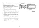
17. G/L Input Connector (G/L IN)
Signals synchronized with the reference signal are
to be supplied to this connector when the camera is
to be synchronized with the reference signal BB.
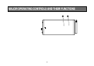
18. Cable Clamp
Clamp the DC Power Supply Cable (AW-CA4T1)
connected to the DC 12 V Input Connector to pre-
vent it from slipping out.
19. Optional Card Slot
Slot for inserting an optional card. For details, refer
to the manual for optional cards.
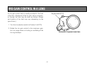
15. Power Indicator
Red LED lamp lights to indicate that the specified
DC power is supplied to the camera.
16. DC 12 V Input Connector (DC 12V IN)
12 V DC is supplied through the optional DC power
supply cable (AW-CA4T1).
(Recommended AC adaptor: AW-PS505)
1. Connect this to a DC 12 V class 2 power supply
only.
2. To prevent fire or shock, the UL listed wire
VW-1, style 1007 should be used as for the cable
for DC 12 V Input Connector.
Cautions
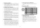
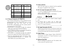
1
2
3
4
5
6
7
8
9
10
1112
Pin No.
Signal
Focus Mode
1 Position/Speed
/Auto Focus
2
Zoom Mode
Position/Speed
3 GND
4
Iris
Remote/Camera
5 Iris Control
6 Lens Power
Pin No.
Signal
Signal Control
7
(+5.0 V)
8 Focus Control
9 Zoom Control
10
Iris Mode
Position/Speed
11 +V (+7.5 V)
12 –V (+2.5 V)