


115
7
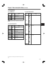
Chapter 7 Menu description tables
(continued)
The underlining in the variable range column indicates the setting in the preset
mode.
RC MENU DISP. ON
OFF
For the setting to display the menu in the
viewfinder screen when the remote control
unit is connected to the unit.
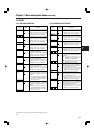
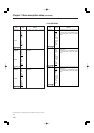
7-4 VF
7-4-1 VF DISPLAY
Item
Variable
range
Remarks
DISP CONDITION NORMAL
HOLD
NORMAL:
The statuses are displayed at all times.
HOLD:
The statuses are displayed only when the
MODE CHECK switch is pressed.
DISP MODE 1
2
3
For setting the display mode.
This sets what is displayed in the viewfinder
screen when the state of the unit is changed.
For details, refer to “4-7-4 Display modes
and setting changes/ adjustment result
messages.”
VF OUT Y
NAM
R
G
B
For selecting the video signals to display in
the viewfinder screen.
Y: Luminance signal
NAM:The signal with the highest level
among the R, G and B signals is
output.
R: R channel signal
G: G channel signal
B: B channel signal
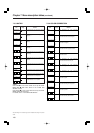
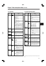
VF DTL 0
:
5
For setting the detail level of the viewfinder
screen.
If it is set to “0”, it has the same detail as the
main line system signals.
If it is set to “5”, it has about double of details
of the main line system signals.
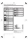
ZEBRA1 DETECT 0%
:
70%
:
109%
For setting the ZEBRA1 detection level (IRE
level).
ZEBRA2 DETECT 0%
:
85%
:
109%
For setting the ZEBRA2 detection level (IRE
level).
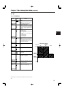
ZEBRA2 ON
SPOT
OFF
For selecting ON or OFF for ZEBRA2 or
selecting SPOT.
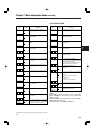
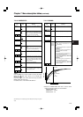
LOW LIGHT LVL OFF
10%
15%
20%
25%
30%
35%
For setting how much lower the camera’s
input light quantity should be in order for
“LOW LIGHT” to be displayed.
MARKER/
CHAR LVL
50%
60%
70%
80%
90%
100%
For setting the brightness of markers and
characters in the viewfinder screen.
CUFR
CUFR
CUFR
CUFR
CUFR
CUFR
CUFR
CUFR
CUFR
CUFR
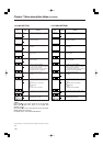
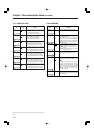
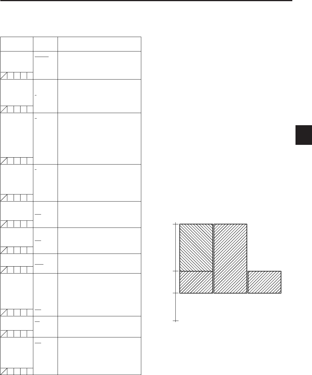
Zebra pattern display
Video level
SPOTOFFON
109%
0%
ZEBRA 2
DETECT
ZEBRA 2
ZEBRA 1
DETECT