


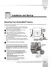
Meet Your CameraMan
1-10 CameraMan
1-CCD Camera System Installation and Operations Manual
CameraMan
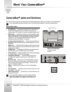
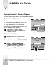
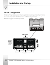
Jacks and Switches
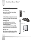
All of the connection jacks and configuration switches described below appear on the back of your CameraMan
.
!
Do not use telephone cords or jacks for any of the following connections. They are wired differently.
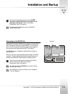
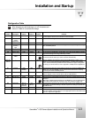
Connection Jacks
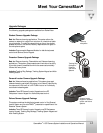
• PVI COM Jack – A standard 6-conductor RJ-11 jack used by
ParkerVision keypads as a communication interface to the
camera system. For example, a hard-wired keypad attaches here.
• RS-485 Jack – A standard 4-conductor modular telephone jack
used for RS-485 communications between the camera and other
ParkerVision devices. You can use this jack to network multiple
cameras or to connect appropriate ParkerVision-approved
peripherals using a ParkerVision T-connector.
• Auxiliary Communication Port – Provides communications to
select ParkerVision peripherals and provides capability for future
expansion.
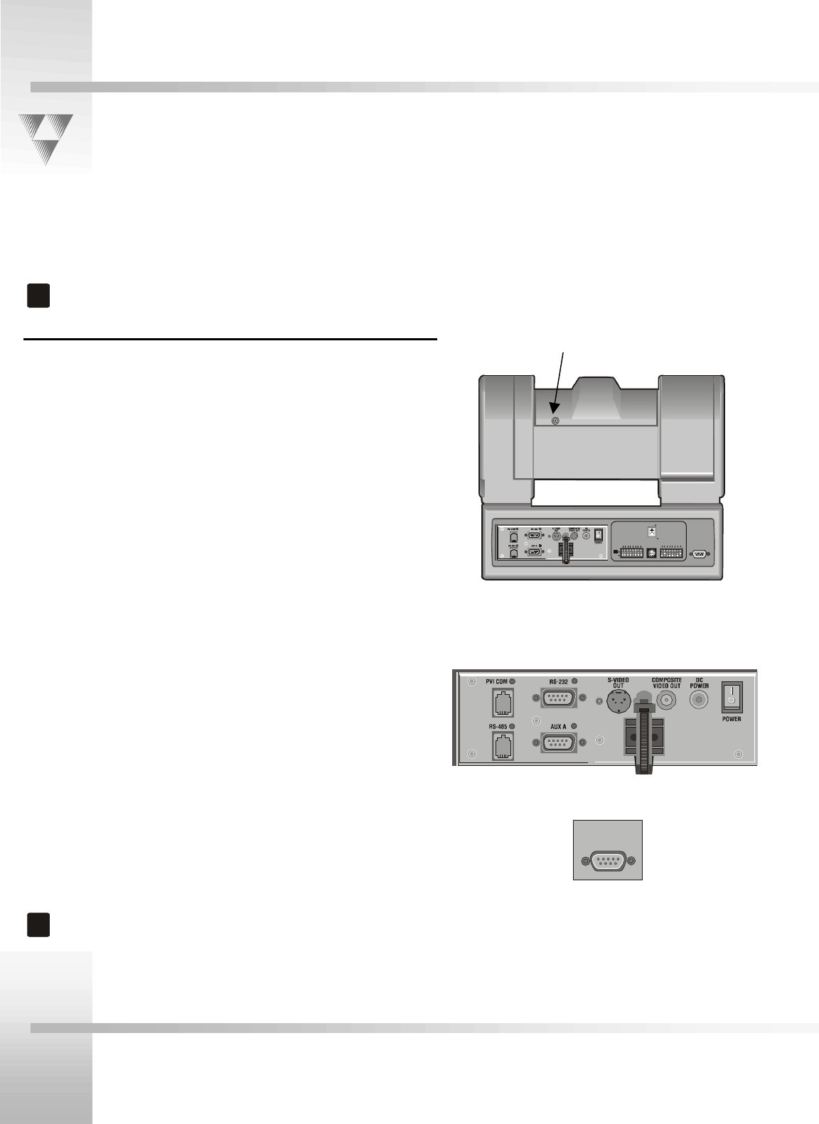
• RS-232 Port – A standard DB-9 female connector that provides
RS-232 communications to external devices such as PCs or other
vendor control systems.
• S-VIDEO Jack – A standard min-DIN jack that provides direct
S-VIDEO video output. S-VIDEO cable is not provided.
• Cable Restrainer – Helps keep cables from becoming dislodged
or hindering the pan and tilt of the camera.
• Composite Video Jack – A standard BNC-type jack that
provides direct composite video output. Video cable is not
provided.
• DC Power Jack - Power input for the CameraMan
camera.
Plug only a ParkerVision power supply (included) into this jack.
Do not use any other type of power supply. This item is not
used with Presenter Systems.
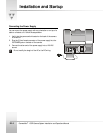
• Power – Use this switch to power on/off the CameraMan
camera.
• Tally Light Port – Provides output and external control for the
CameraMan
Tally Light.
• Gen Lock Connector – Provides input and external control for
setting up Gen Lock.
!
If you purchased a Presenter or Deluxe Camera System,
refer to their respective manuals for information on the
Main Docking Station that replaces the connector box.
UP
DOWN
SWITCH BANK
-A-
SWITCH BANK
-B-
1234567812345678
S-VIDEO
COM POSI T E
BASE UNIT
ADDRESS
TALLY LIGHT
INTERFACE
TALLY LIGHT
INTERFACE
Back of 1-CCD camera with
connector box attached and
configuration plate
removed.
Ports and Jacks
Tally Light Port
Gen Lock Connector