


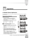
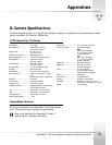
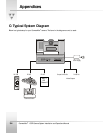
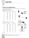

Appendices
CameraMan
1-CCD Camera System Installation and Operations Manual 3-5
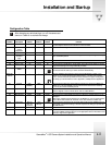
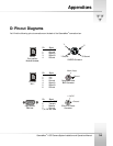
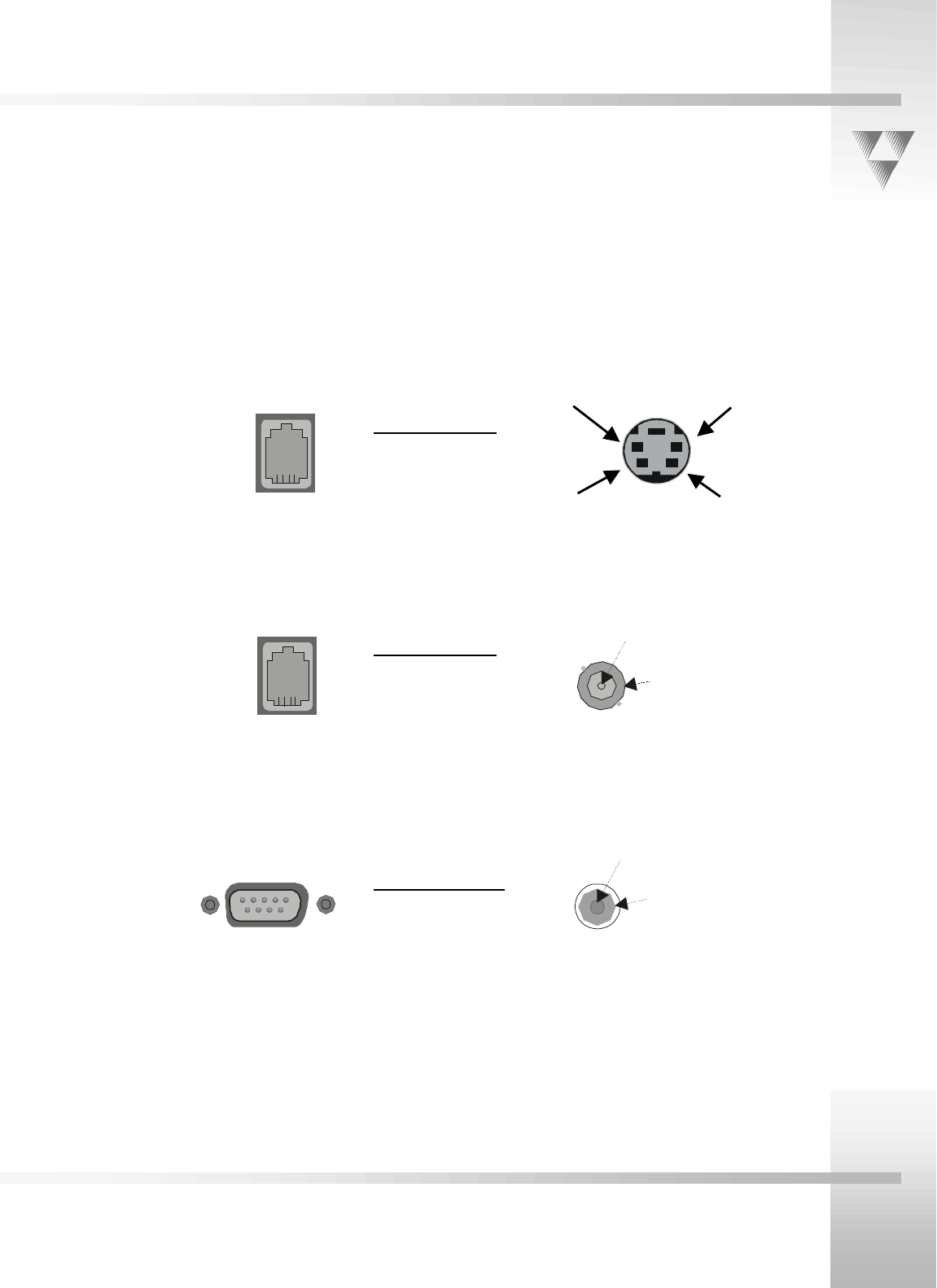
D: Pin-out Diagrams
You'll find the following pin-out connections on the back of the CameraMan
connection box.
4
1
RS-485
Four position
Module Handset
6
1
PVI COM
RJ-11
Y
C
Y Ground
C Ground
S-VIDEO Connector
Video (1Vpp)
Ground
Composite Video
BNC Connector
+ 18v DC
Ground
5.5mm DC Power
Connector
1
6
5
9
9-pin Female
DB-9 Sub
Pin Signal___
1Ground
2Signal A
3Signal B
4Ground
Pin Signal___
1 12v
2 12v
3Ground
4Signal A
5Signal B
6
G
r
ou
n
d
Pin Signal____
2Transmit
3 Receive
5Ground
1,4, 6-9 Not used