


Installation and Startup
2-12 CameraMan
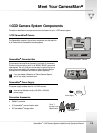
1-CCD Camera System Installation and Operations Manual
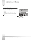
Connecting to the Camera System
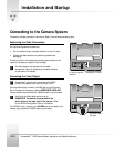
This section provides connection instructions. Refer to the left-side connection ports.
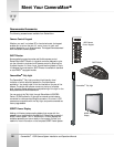
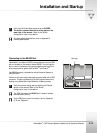
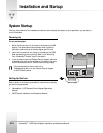
Restraining the Cable Connections
For the following camera connections:
• Run the cables through the cable restrainer from left to right.
• Tighten the cable restrainer to prevent any cables from
dislodging.
This should result in the cables being located approximately in the
center of the camera, instead of near the edge.
!
To relieve stress on the camera and the cable
connections, fasten all cables using the cable restrainer
on the back of the camera.
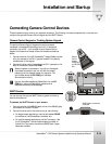
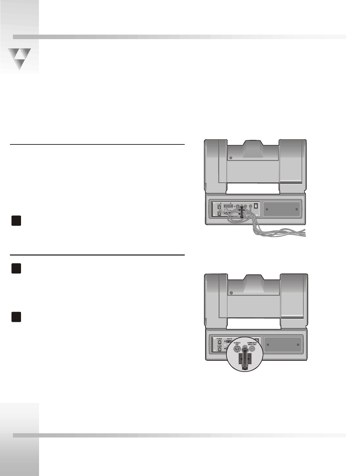
Connecting the Video Output
!
CameraMan
supports both composite and S-VIDEO
formats, although you can use only one at a time.
For composite format, connect to the BNC jack on the Connector
Box on the back of the camera, labeled COMPOSITE VIDEO OUT,
using a standard coaxial cable with a BNC connector (not provided).
!
Verify that the Video Select switch is set to
COMPOSITE. The switch is located behind the
switch plate on the back right of the camera. Refer
to the "Switch Configuration" topic in this section.
For S-VIDEO format, connect to the S-VIDEO jack on the back of the
camera using a standard S-VIDEO cable (not provided).
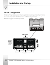
PVI COM RS -23 2
AUX A
S-VIDEO
OUT
COM POSI TE
VID EO OUT
DC
POWER
POWER
RS-48 5
Feed cables from left
to right through the
restrainer.
S-VIDEO and
Composite Video
Out Jacks