Installation and Startup
CameraMan
1-CCD Camera System Installation and Operations Manual 2-17
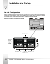
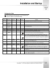
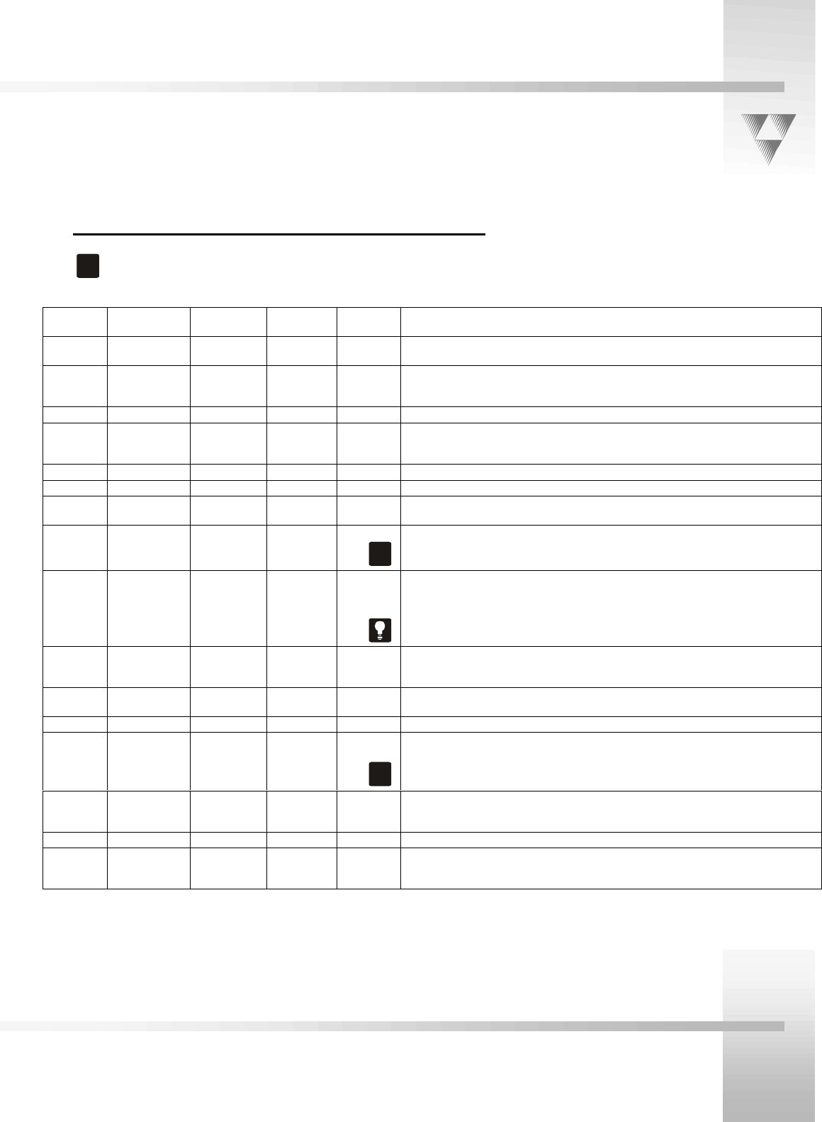
Configuration Table
!
After changing any switch settings, turn off the camera and
then turn it back on to activate the change.
Switch
Number Description
DOWN
Position
UP
Position
Factory
Default Function
A1 Lens Select Normal Adapter DOWN
Use this switch with Personal Locator and Deluxe Camera Systems to indicate the use
of a lens adapter. Refer to their manuals for more information.
A2 Sub-carrier
Coarse
Adjustment
0° 180°
DOWN
Use this switch to change the sub-carrier phase from 0° to 180°.
A3 -- -- -- DOWN NOT USED
A4 Lens
Converter
Type
Wide -- DOWN Use this switch with switch A1 to select the type of lens adapter being used. Always
set to the DOWN position.
A5 & A6 -- -- -- DOWN NOT USED
A7 Baud Rate 9600 19200 UP Use this switch to configure the camera's baud rate for the RS-232 and RS-485 ports.
A8 Memory Lock Lock Unlock UP For the majority of applications, use this switch in the UP (Unlock) position to prevent
programmed settings from being accidentally overriden.
Video Out Composite/S-
VIDEO
Composite S-VIDEO DOWN
!
Use this switch to set the video source to composite (DOWN) or S-VIDEO (UP).
You must choose one source, you cannot use them simultaneously.
Base Unit
Address
-- -- -- Zero (0) Use this 16-position rotary switch to set the unique identification number of your
camera. If you use the optional keypad, SHOT Director, or another control system,
refer to the documentation provided with those accessories for proper configuration.
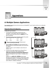
For setting up a camera network, refer to Appendix A, Multiple Camera Applications.
B1 Protocol
High
Reliability
Basic DOWN
Use this switch to select the communication protocol to be used by the RS-232 and
RS-485 ports. The High Reliability protocol includes some advanced error checking
that is not performed in the Basic protocol.
B2 Data Source Local Remote DOWN Use this switch to determine whether the camera will receive data from a local source
such as a keypad, or from a remote source, such as a SHOT Director.
B3 Digital Zoom Off On DOWN Use this switch to turn on or off the digital zoom feature.
B4 RF Command Enable Disable DOWN
!
Use this switch to enable/disable the camera to respond to commands sent from an
RF Keypad.
When using multiple cameras networked on the RS-485 bus, only one camera should
have its RF receiver enabled. Set switch B4 on the other cameras to Disable (UP).
B5 Preset Save Manual
Gain, Iris
and Focus
Auto
Settings
DOWN Use this switch to determine how the preset settings will be saved. DOWN saves your
Manual Gain, Iris and Focus settings. UP saves only the Auto settings for presets and
autoTRACK views.
B6 & B7 -- -- -- DOWN NOT USED
B8 Interlink Enable Disable DOWN Use this switch in multi-camera applications. The DOWN position passes all commands
through the RS-485 communication bus to the appropriate camera. This switch has no
effect in a single camera application.


