


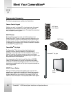
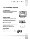
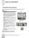
CameraMan
1-CCD Camera System Installation and Operations Manual 2-11
Installation and Startup
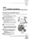
Mounting Your CameraMan
Camera
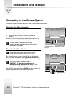
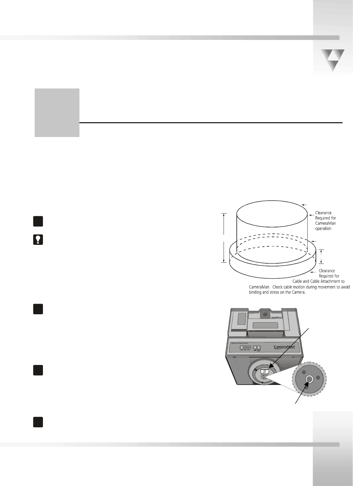
You can mount your CameraMan
camera on any flat, non-slick, nonmetal surface with a minimum supporting area of 8"
x 8". Follow the instructions below:
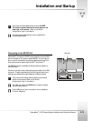
1. Check your selected camera location to ensure that you have
enough camera and cable clearance space for the CameraMan
camera to pan and tilt without obstruction.
!
Do not mount the camera upside down or with more
than a 10 degree angle from horizontal.
Refer to Appendix E, Field of View Specifications, to
assist you with positioning the CameraMan
camera to
achieve optimum optical views.
2. Locate the zero-degree position mark labeled "Front" on the
bottom of the base unit. This mark helps ensure that the base
unit is calibrated correctly.
Point this indicator mark in the direction that best reflects the
center of travel for the camera. (This is usually the center of the
room.)
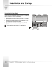
!
Lift the unit by its base, not by its tilt assembly.
3. To ensure that the mounting surface is not prone to vibrations,
fasten the camera to a flat, rigid surface using a 1/4"-20 UNC
cap screw that does not extend into the base platform by
more than 0.4". (The cap screw is not included.) To use a 3/8"-
16 UNC cap screw, remove the insert provided in the mounting
screw hole.
!
To avoid overtightening, tighten this screw by hand. If
necessary, use a non-hardening threadlock to prevent
the screw from loosening. Overtightening can prevent
the camera from panning properly and may
damage the unit.
Never attempt pan or tilt movement by hand.
Always use a control device.
!
Always operate the camera indoors and follow the
temperature and humidity specifications outlined in
Appendix B, Camera Specifications.
Section
2
x
x
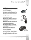
12.0”
22.0”
3.0”
18.0”
3/8"-16 UNC
Mounting Screw
Hole with 1/4"-20
UNC insert.
Zero degree
pan position
mark