


Installation and Startup
2-16 CameraMan
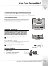
1-CCD Camera System Installation and Operations Manual
Switch Configuration
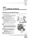
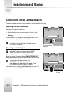
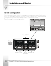
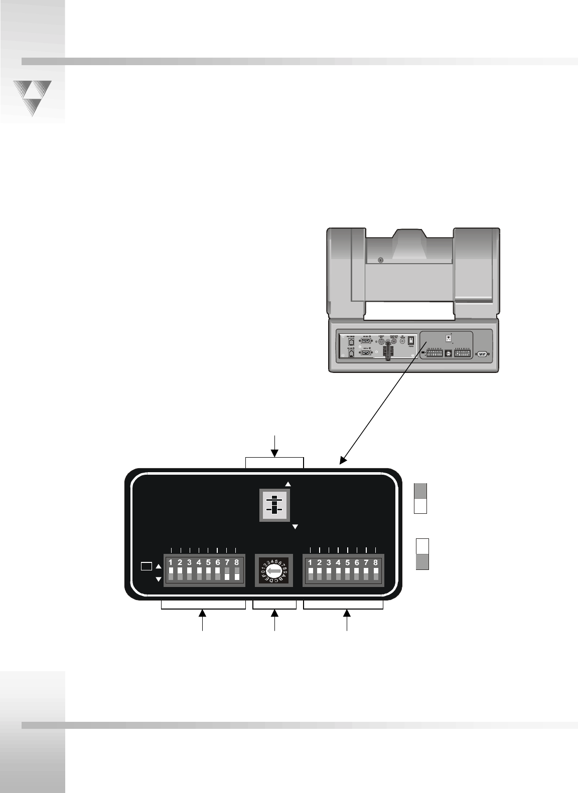
Now that you have connected your camera to the power supply and control devices, you need to configure the camera
to work in your specific application. To begin, remove the switch plate on the back right side of the camera by removing
the two screws holding it in place. Behind the plate you will see all of the configuration switches.
Refer to the next page for a table describing the switches.
UP
DOWN
SWITCH BANK
-A-
SWITCH BANK
-B-
12345678
12345678
S-VIDEO
COMPOSITE
BASE UNIT
ADDRESS
Up
Dow n
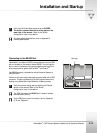
This diagram
shows the
default switch
configuration
of the camera
as shipped.
UP
DOWN
SWITCH BANK
-A-
SWITCH BANK
-B-
12345678
12345678
S-VIDEO
COM POSI T E
BASE UNIT
ADDRESS
TALL Y LIGHT
INTERFACE
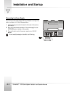
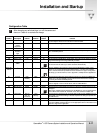
Switches A1 – A8 Base Unit Switches B1 – B8
Address Switch
Video Out Switch