


12 C2601M-C (3/07)
Connecting Devices to the DX4000
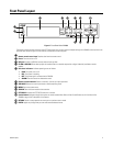
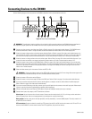
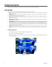
Use the following diagram of the rear panel of the DX4000 to determine how to connect devices to the unit.
Figure 5. Rear Panel of the DX4000
WARNING: To avoid electric shock, turn off the unit and unplug it while connecting devices to the DX4000. Adequate ventilation is
required for proper operation of the DX4000. Allow two inches of space above the unit and on each side for air circulation.
ì Connect up to four cameras at the video inputs. Refer to Table A on page 13 for video coaxial cable distances. The DX4000 features
automatic termination of video if no loop out cables are attached. Remove all unused cables from the video output ports.
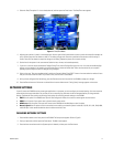
î If desired, connect analog monitors to the video outputs (looping). Refer to Table A on page 13 for video coaxial cable distances. You
must terminate all monitors. If you connect a single monitor to an output, terminate the monitor at 75 ohms. If you connect more than
one monitor to an output, terminate the farthest monitor at 75 ohms, and terminate the others at Hi-Z. Remove all unused cables.
ï If desired, connect an analog monitor to the main monitor output. Refer to Table A on page 13 for video coaxial cable distances. If you
connect more than one monitor to an output, terminate the farthest monitor at 75 ohms, and terminate the others at Hi-Z.
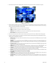
ñ If desired, connect a spot monitor to the DX4000. Refer to Table A on page 13 for video coaxial cable distances. If you connect more
than one monitor to an output, terminate the farthest monitor at 75 ohms, and terminate the others at Hi-Z. Note that you can view live
video from a spot monitor. To search for and play back video or to configure the DX4000, you must be working at the unit and main
monitor or at a remote computer.
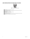
ó Select the video stream type for the cameras. Choices are NTSC or PAL.
r
If desired, connect a VGA monitor to the VGA port.
s
If desired, connect a monitor that accepts S-Video to the SVHS port. Refer to Table A on page 13 for video coaxial cable distances.
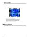
t If you want to receive audio transmissions from the remote agent on a computer, connect an audio cable to the audio output jack.
Refer to Table A on page 13 for video coaxial cable distances.
u If you want to record audio along with video, connect up to four audio feeds from the cameras to the audio input jacks. Before record-
ing audio, consult your location’s applicable laws regarding audio surveillance.
~í
Connect an Ethernet cable at the Ethernet (TCP/IP) port to connect the DX4000 to remote users across a network.
~â Connect alarm inputs, relay outputs, and PTZ connections as follows:
Alarm inputs: You can have one alarm for each camera. Connect one alarm lead to the A1, A2, A3, or A4 input, and the other alarm
lead to the ground input. Alarms can be programmed for normally open or normally closed inputs.
Relay outputs: Connect a relay to the normally open (NO), normally closed (NC), or common (COM) outputs. The relay is rated for I A
at 30 VDC or 0.5 A at 125 VAC.
PTZ connections: Connect the leads for controlling a PTZ camera from the RX+ and RX- leads on the camera to the TX+ and TX- con-
nectors on the DX4000. To connect several cameras with PTZ capabilities, daisy-chain the cameras.
SEQ
L
12
1 2 3 4
2
3
4
1
NTSC PAL
2
3
4
1
L
ᕡ
ᕢ
ᕣ ᕦ ᕩ ᕫᕵ
ᕤ ᕧ ᕨ ᕫᕾ ᕫᕶ ᕫᕷᕥ
WARNING: Changing the video stream type from NTSC to PAL reformats the hard disk. Do not change video stream types until a
recorded video has been backed up to CD or a removable USB flash memory device.