14 C2953M-A (5/09)
WIRING
CAT5 CABLE
Connect a Cat5 cable to the RJ-45 network connector. The 8-pin connector includes video and PoE for the camera. PoE (IEEE 802.3af) injects
power over the same cabling that carries the network data, eliminating the need for a separate power supply. This simplifies the installation and
operation of the camera without any degradation of network performance.
NOTE: The camera will autosense and work with either a crossover cable or straight cable.
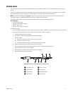
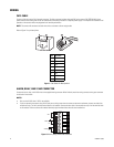
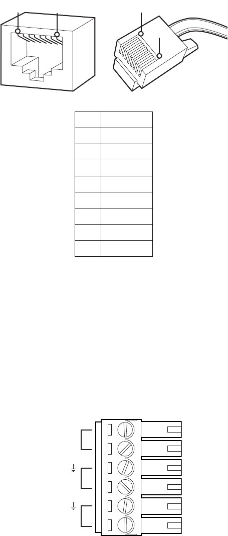
Refer to Figure 7 for pin descriptions.
Figure 7. Cat5 Cable Pin Descriptions
ALARM, RELAY, AND 24 VAC CONNECTOR
Connect the alarm, relay, and 24 VAC wires to the supplied mating connector. When finished, attach the mating connector to the green connector
on the back of the camera.
NOTES:
• Only use the 24 VAC wires if PoE is not available.
• If you are operating the camera using 24 VAC and you are wiring more than one camera to the same transformer, connect one side of the
transformer to pin 1 of the 2-position terminal block on all modules. Connect the other side of the transformer to pin 2 of the terminal block
on all modules. Failure to connect all modules identically might introduce video noise for some installations.
Figure 8. Alarm, Relay, and 24 VAC Connector
Pin Function
1TX+
2TX-
3 RX+
4PoE 1-2
5PoE 1-2
6 RX-
7PoE 3-4
8PoE 3-4
1
2
3
4
5
6
7
8
1
2
3
4
5
6
7
8
8
8
1
1
24V~
RELAY
R1
ALARM
A1


