


C2953M-A (5/09) 15
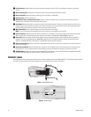
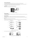
Connecting a Relay Device
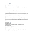
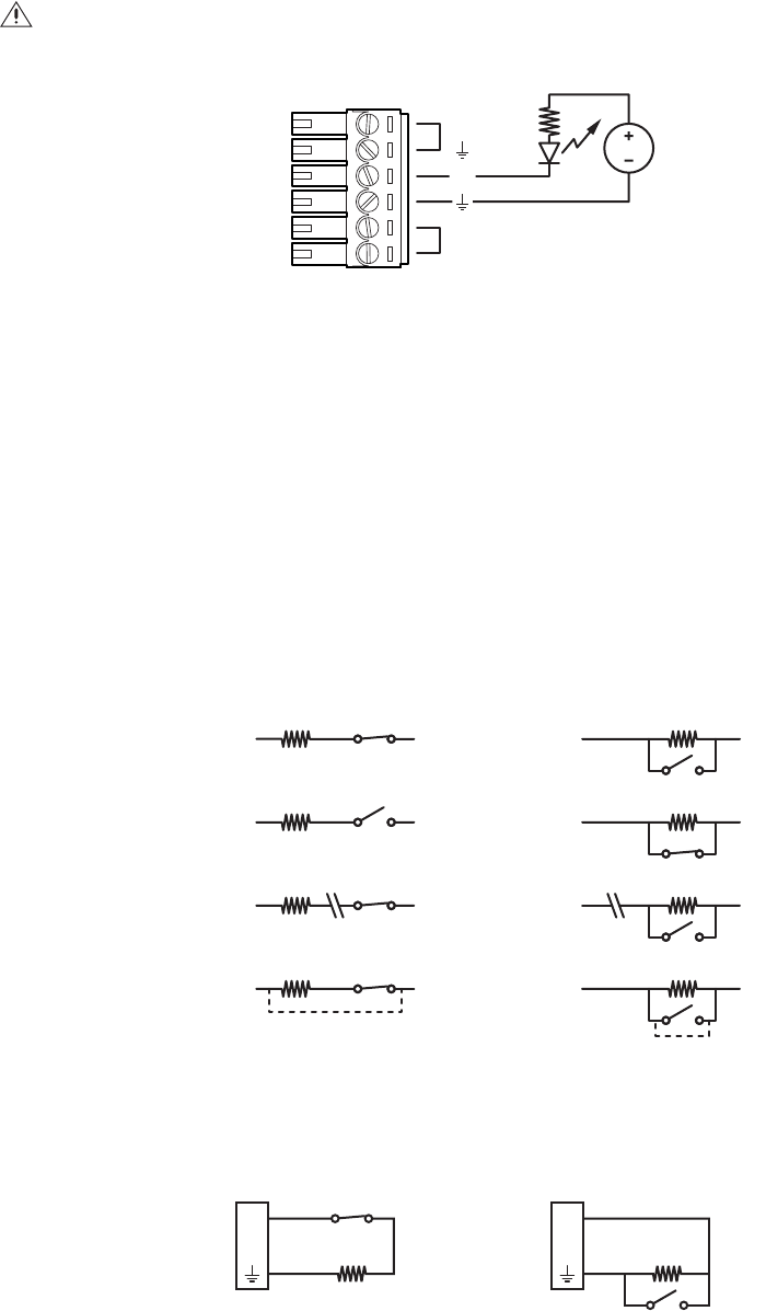
The camera has an output for activating an external device. It supports both momentary and continuous relay operation.
You can operate the relay interactively during an active connection, or it can operate automatically to coincide with certain events. Typical
applications include turning on lights or other electrical devices or activating a door, gate, or lock.
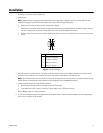
Figure 9 shows how to wire the relay with its power source to the camera.
Figure 9. Relay Wiring
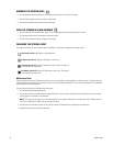
Connecting Alarms
The camera provides an alarm input for external signaling devices, such as door contacts or motion detectors. Both normally open and normally
closed devices are supported.
Supervised Alarms
When an alarm is configured as a supervised alarm, the camera maintains a constant electrical current through the alarm circuit
(3.3 VDC, 1 ohm). If the alarm circuit length changes, due to an electrical short or a bypass, the voltage fluctuates from its normal state and
activates an alarm.
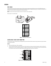
NOTE: Install the 1-kohm resistor as close to the switch as possible.
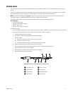
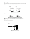
Figure 10 illustrates the alarm and no alarm conditions of a supervised alarm input. Whether the alarm is normally closed or normally open,
neither a cut nor a bypass can defeat these alarms.
Figure 10. Supervised Alarm Conditions
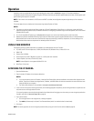
Figure 11 illustrates the wiring configuration for supervised alarm inputs.
Figure 11. Supervised Alarm Input Wiring
WARNING: Do not exceed the maximum rating of 12 VDC, 0.15 A.
12 VDC, 150 mA MAX
24V~
R1
A1
+V
+V
+V
+V
+V
+V
+V
+V
BYPASS
CUT
BYPASS
CUT
1 KΩ
1 KΩ
1 KΩ
1 KΩ
1 KΩ
1 KΩ
1 KΩ
1 KΩ
GND
ALARM
GND
ALARM
GND
NO ALARM
GND
ALARM
GND
ALARM
GND
ALARM
GND
NO ALARM
GND
ALARM
NORMALLY OPENNORMALLY CLOSED
1 KΩ
A
1
1 KΩ
A
1
NORMALLY OPENNORMALLY CLOSED