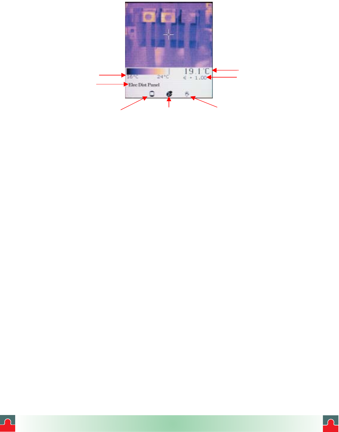
Figure 8. Normal Mode
Mode icon Palette iconLCD backlight icon
Target Temperature
Emissivity value
Location name
Temperature scale
Take time to experiment with the imager and become familiar with how the thermal image is
updated on the display as you aim the imager at different targets with different thermal
patterns. Notice how images display in varying colors, which are related to the different
target temperatures. The color scale at the bottom of the thermal image shows the minimum
and maximum temperature value in the thermal scene at any moment. These values will
change as you point the imager at other targets, or if the temperatures of the current target
change. The sequence or progression of different colors along the color scale indicates the
distribution of the different temperatures on the thermal scene. Notice how the colors along
the beginning of the color scale represent lower temperatures and colors along the end of
the color scale represent higher temperatures.
Note:
At this point you probably have noticed that the image freezes briefly from time to
time while an hourglass icon is briefly displayed. This is a normal process that
happens when the unit momentarily shuts down the optical channel to eliminate
offset errors. This is a recalibration sequence that begins immediately after the unit
is turned on. Recalibration occurs at 5 seconds, then 10 seconds, then 20 seconds,
then 30 seconds and then finally at every other minute. It is a good idea to keep the
unit On if you are using it constantly over a period of time to avoid resetting the
recalibration procedure counter.
The ThermoView imager settings can be customized for your particular application. The
following sub-section reviews the settings and controls.
July 1, 2003 - 17 - Version 1.0
i
i
Tel: (01943) 602001- WWW.ISSLTD.CO.UK - Fax: (01943) 816796


