PG-FP5 V2.13 PROGRAMMING GUI USAGE
R20UT2924EJ0200 Rev.2.00 Page 46 of 71
Mar 02, 2015
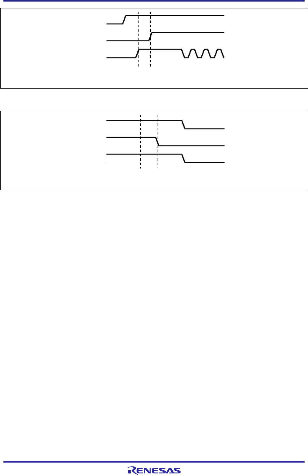
(a) Transition to the flash memory programming mode
(1): Put the transition to the flash memory programming mode on hold.
(2): Detect the rising edge of the signal entering the RESET
¯¯¯¯¯¯
pin.
(b) Ending the flash memory programming mode
(1): Put the ending of the flash memory programming mode on hold.
(2): Detect the falling edge of the signal entering the RESET
¯¯¯¯¯¯
pin.
Figure 1.64 Detection Timing of Target Reset
[Run after Disconnect] check box
If this check box is selected, the RESET
¯¯¯¯¯¯
signal level changes from low level to Hi-Z after each command. Note that
when the “Reset option of Run after Disconnect” is set to Pull-up with the [FP5 Manager] dialog box, the signal will go
from low level to Pull-up. If this check box is not selected, the RESET
¯¯¯¯¯¯
signal changes to low level after each command
is finished. This check box becomes available if the [On Target] check box in the [Supply voltage] area is selected. If
selected, the written program can be automatically executed after each command is finished.
VDD
RESET
¯¯¯¯¯¯
FLMD0
or
VPP
(1)
(2)
VDD
RESET
¯¯¯¯¯¯
FLMD0
or
VPP
(1)
(2)


