


− 11 −
Message
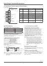
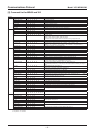
OSD Zoom Ratio A0 14 00 0p CS FF p: Zoom magnification display
Zoom Ratio Position A0 14 01 p 0q CS FF Zoom magnification display position
p: x-position (0-19)
q: y-position (0-11) (Initial value: x: 19 y: 11)
Direction A0 14 02 0p CS FF p: Orientation / angle information display (1: ON/0: OFF) (Note 4)
Direction Position A0 14 03 0p 0q CS FF Positioning of the orientation / angle information display p: x-position (0-11) q: y-position (0-11) ( (Initial
value: x: 1 y: 11
)
Set North A0 14 04 0p CS FF p: Setting the current position to the home position (Orientation: North, PAN angle: 0˚)
(1: ON/0: PRESET
)
(Note 4)
Rom Version Display A0 14 10 0p CS FF p: Version display (1: ON/0: OFF) (Note 6)
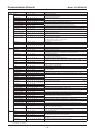
Camera
ID
OFF A0 15 00 CS FF Camera ID display (ON/OFF)
ON A0 15 01 CS FF
ID SET (ASCII code) A0 15 09 p q r s t u Camera ID settings (Note 5)
v w CS FF
ID X-Position + A0 15 0B CS FF Setting the positioning of the Camera ID display (horizontal)
ID X-Position - A0 15 0C CS FF
ID Y-Position + A0 15 10 CS FF Setting the positioning of the Camera ID display (vertical)
ID Y-Position - A0 15 11 CS FF
Title A0 15 20 0p CS FF p: Title display (1: ON/0: OFF)
Title Set (ASCII code) A0 15 21 p q r s t u Title settings (Note 5)
v w CS FF
Title Position A0 15 22 0p CS FF p: Positioning of the title display (1: displayed on the next line from the ID / 0: displayed on the same
line)
EEPROM
Access
EEPROM Access A0 19 01 0p 0q 0r 0s 0t CS Writes the values to the EEPROM
pqr: Address 0-2047 st: Data 0-255
FF
Baudrate 19200 bps A0 1A 00 CS FF
UART communication speed settings
Enables after camera restart
9600 bps A0 1A 01 CS FF
4800 bps A0 1A 02 CS FF
2400 bps A0 1A 03 CS FF
38400 bps A0 1A 04 CS FF
ALARM ALARM OUT OFF A0 1F 00 CS FF
External alarm output settings (For zoom cameras)
ALARM OUT ON A0 1F 01 CS FF
LINE OUT OFF A0 1F 0A CS FF
Alarm output settings to controller (For zoom cameras)
LINE OUT ON A0 1F 0B CS FF
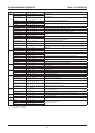
DAY/
NIGHT
D/N COLOR A0 28 00 CS FF
○
Color Mode
D/N BLACK/WHITE A0 28 01 CS FF
○
Black and White Mode
D/N AUTO A0 28 02 CS FF
○
Color/Black and White Auto Switch Mode (Note 3)
D/N BURST OFF A0 28 03 CS FF
○
Burst Settings ON/OFF
D/N BURST ON A0 28 04 CS FF
○
D/N LEVEL SET A0 28 05 0p CS FF
○
p: Color/Black and White Switch Level Settings (0: LOW, 1: MID, 2: HIGH, 3: ADJ)
Switch level LOW: Dark – High: Bright ADJ: Manual setting
D/N ADJ DIRECT (C->B/W) A0 28 06 0p CS FF
○
Switch Level LOW: Dark-HIGH: Bright
ADJ: Manual Settings
p: Color Black and White Switch Level Manual Settings 0-6
Larger value switches darker sections (Initial value: 4)
D/N ADJ DIRECT (B/W->C) A0 28 07 0p CS FF
○
p: Black and White Color Switch Level Manual Settings 0-6
Larger value switches darker sections (Initial value: 4)
D/N FOCUS SET (AUTO) A0 28 08 0p CS FF
○
p: Focus mode settings during D/N AUTO black and white, 0: Near infrared wavelength compensation
(MODE1), 1: Corresponds to optical wavelengths (MODE2)
D/N FOCUS SET (B/W) A0 28 09 0p CS FF
○
p: Focus mode settings during D/N BLACK/WHITE, 0: Near infrared wavelength compensation
(MODE1), 1: Corresponds to optical wavelengths (MODE2)
DNR OFF at AGC ON A0 28 14 CS FF
DNR ON/OFF (Note 3)
DNR ON at AGC ON A0 28 15 CS FF
D/N Filter Slide Time A0 28 16 p CS FF
○
p: Changes the D/N filter slide time. (5 – 20 seconds) [Initial value: 0 seconds]
Stabilizer Stabilizer OFF/ON A0 33 00 0p CS FF p: Stabilizer (Stabilizing function) ON/OFF (0: OFF/1: ON) * Only VCC-MD700/800 series
Stabilizer Level A0 33 01 0p CS FF p: Setting the level of the Stabilizer Level (0: Low 1: Middle 2: High) default: 1
* Only VCC-MD700/800 series
Auto
Pursuit
Auto Pursuit OFF/ON A0 34 00 0p CS FF p: Auto Pursuit ON/OFF (0: OFF/1: ON)
Auto Pursuit Sensitivity A0 34 01 0p CS FF p: Sets the sensitivity to brightness variation when motion is detected
1-F (High sensitivity – Low sensitivity)
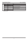
Communications Protocol
Model: VCC-MD800/700/600/500
CS: Checksum
FF: Terminator
○
: Only MD800/MD600 can be used.