


− 33 −
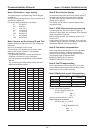
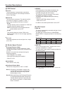
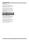
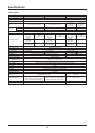
Setting the Mask Position (Area Mask Position Set)
x-Coordinate
Start Position
x-Coordinate
End Position
y-Coordinate
Start Position
y-Coordinate
End Position
x
y
If the coordinates increase by 1, the position moves
by 4 horizontal pixels and 2 vertical lines.
The upper left and lower right horizontal and vertical
coordinates (1 byte each) are each divided into upper
and lower 4 bits.
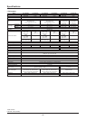
Example) Setting the mask position according to the
following parameters during NTSC
Mask Number 1
x-Coordinate Start Position 0x48
y-Coordinate Start Position 0x1C
x-Coordinate End Position 0x82
y-Coordinate End Position 0x40
Pan Angle 135°
Tilt Angle 45°
Setting Procedures
1. Mask Position (x, y coordinates) Settings
(Area Mask Position Set)
A0 10 09 01 04 08 01 0C 08 02 04 00 CS FF
2. Mask Angle Settings (only during PTZ)
(Area Mask Degree Set)
A0 10 11 01 05 04 06 01 0C 02 CS FF
3. Setting Mask ON (Area Mask ON)
A0 10 01 01 CS FF
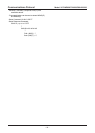
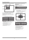
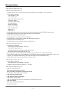
Settings Increasing Privacy Mask Accuracy
(MD800-MD500)
Area Mask Position Center Set
Command: A0 10 0A 0p 0q 0r 0s 0t CS FF
Parameter:
p Mask Number (No. 1-15)
qr Mask Width
st Mask Height
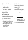
Usage: Sets the mask position mainly according to the
optical.
Note: Set the mask size to sufficiently cover the mask
object. In addition, ensure that the settings are
set on the WIDE end.
The minimum unit of the mask width is 4
horizontal pixels and the minimum unit of the
mask height is 2 vertical lines.
Mask Height
Mask Width
x
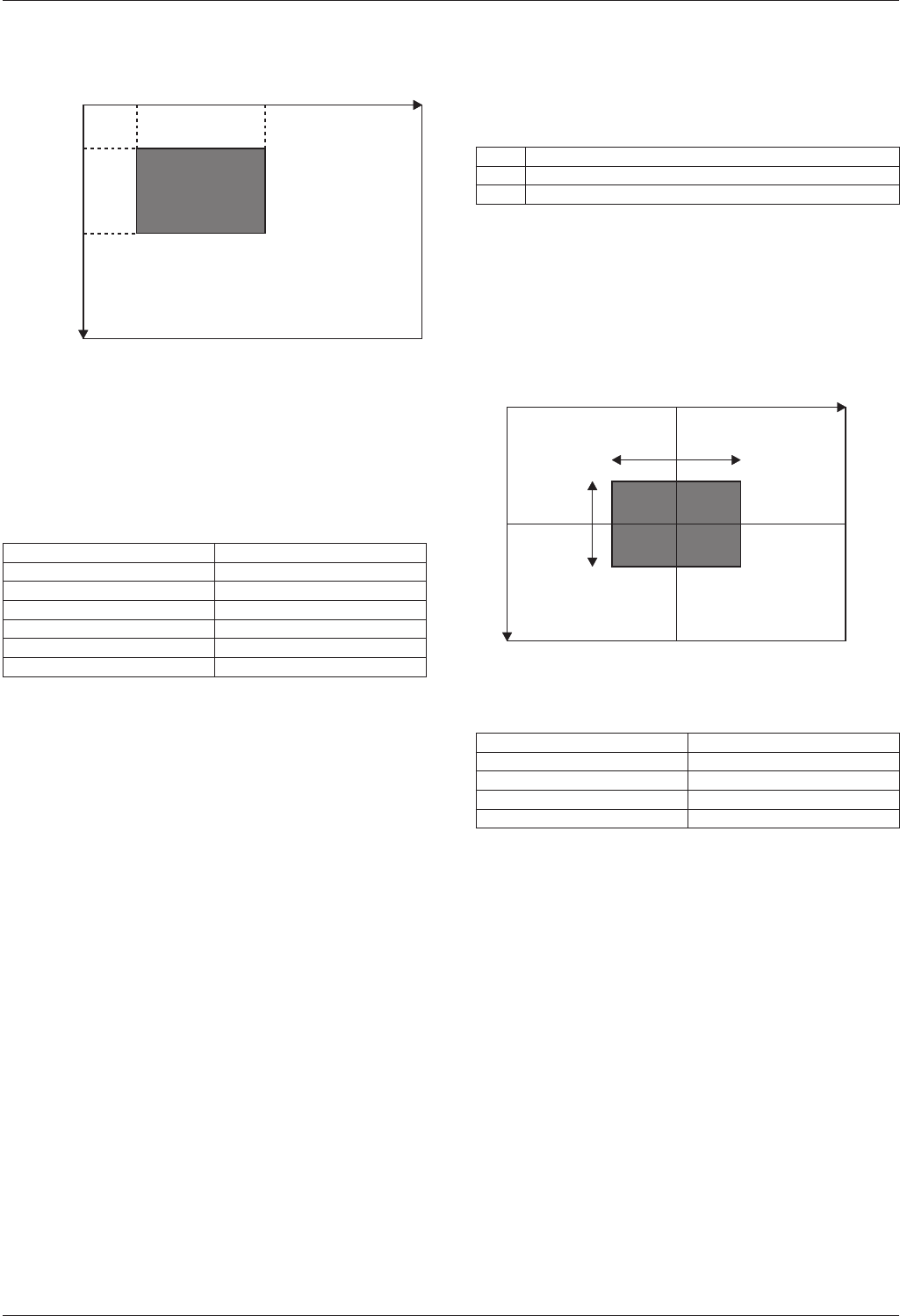
Example) Setting the mask position according to the
following parameters during NTSC
Mask Number 1
Mask Width 0x50
Mask Height 0x3C
Pan Angle 135°
Tilt Angle 45°
Setting Procedures
1. Mask Position (width and height) Settings
(Area Mask Position Center Set)
A0 10 0A 01 05 00 03 0C CS FF
2. Mask Angle Settings (only during PTZ)
(Area Mask Degree Set)
A0 10 11 01 05 04 06 01 0C 02 CS FF
3. Setting Mask ON (Area Mask ON)
A0 10 01 01 CS FF
Function Descriptions