


− 13 −
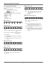
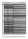
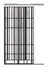
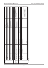
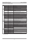
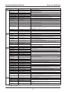
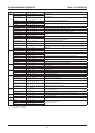
Message Query Command Response Command
Sync L-L Phase Direct 80 09 13 CS FF C0 09 13 0p 0q 0r CS FF Power Source Synchronous Set Value Direct 0-524(NTSC) / 0-624(PAL)
AGC Max Gain at AGC
(
COLOR
)
80 0A 09 CS FF C0 0A 09 0p CS FF AGC MAX Gain Set Value
(D/N camera set value when in COLOR)
p: 0:LOW, 1: NORM, 2: MID, 3: HIGH
Max Gain at AGC
(
BW) 80 0A 0A CS FF C0 0A 0A 0p CS FF AGC MAX Gain Set Value during B/W
p: 0:LOW, 1: NORM, 2: MID, 3: HIGH
Max Gain at AGC
(
AUTO)
80 0A 0B CS FF C0 0A 0B 0p CS FF AGC MAX Gain Set Value during
AUTO
p: 1: NORM, 2: MID, 3: HIGH
Gain Direct
(
COLOR
)
80 0A 13 CS FF C0 0A 13 0p CS FF Gain Settings when COLOR and AGC
are OFF
"0: 0dB, 1: 3dB, 2: 6dB, 3: 9dB, 4: 12dB,
5: 15dB, 6: 18dB, 7: 21dB, 8: 24dB,
9: 27dB, 10: 30dB"
Gain Direct
(
BW
)
80 0A 14 CS FF C0 0A 14 0p CS FF Gain Settings when B/W and AGC are
OFF
"0: 0dB, 1: 3dB, 2: 6dB, 3: 9dB, 4: 12dB,
5: 15dB, 6: 18dB, 7: 21dB, 8: 24dB,
9: 27dB, 10: 30dB"
Gain Direct
(
AGC ON
)
80 0A 15 CS FF C0 0A 15 0p 0q CS FF Current Gain Value (AGC ON) pq: 0-120
(
pq×0.3dB
)
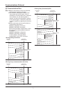
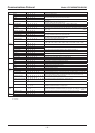
Aperture Aperture V Direct 80 0B 13 CS FF C0 0B 13 00 0p CS FF Vertical Contour Compensation Set
Value
1-15
Aperture H Direct 80 0B 1D CS FF C0 0B 1D 00 0p CS FF Horizontal Contour Compensation Set
Value
1-15
Gamma Mode 80 0C CS FF C0 0C 0p CS FF p: 0:1, 1:0.45, 2:SMART1, 3:SMART2
Mirror Mode 80 0D CS FF C0 0D 0p CS FF
p: 0:OFF, 1:H-Mirror, 2:V-Mirror, 3:HV-Mirror
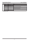
OSD Zoom Ratio 80 14 00 CS FF C0 14 00 0p CS FF Zoom magnification display 0: OFF/1: ON
Zoom Ratio Position 80 14 01 CS FF C0 14 01 p 0q CS FF Positioning of the zoom magnification
display
p: x-position (0-19) q: y-position (0-11)
Direction 80 14 02 CS FF C0 14 02 0p CS FF Orientation / angle information display 0: OFF/1: ON
Direction Position 80 14 03 CS FF C0 14 03 0p 0q CS FF Positioning of the orientation / angle
information display
p: x-position (0-11) q: y-position (0-11)
Set North 80 14 04 CS FF C0 14 04 0p CS FF Angle settings 0: not set / 1: set
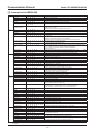
Camera ID ID Code 80 15 09 CS FF C0 15 09 p q r s t u v w CS FF ASCII code for the camera ID (Note 5)
Title 80 15 20 CS FF
C0 15 20 0p CS FF Title display 0: OFF/1: ON
Title Code 80 15 21 CS FF C0 15 21 p q r s t u v w CS FF ASCII code for the title (Note 5)
Title Position 80 15 22 CS FF C0 15 22 0p CS FF Positioning of the title display 1: 2 line display / 0: 1 line display
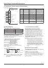
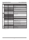
Privacy
Masking
Mask Position 80 10 09 0p CS FF
C0 10 09 0p 0q 0r 0s 0t 0u 0v 0w 0x CS FF
Privacy Mask Position Refer to the Privacy Mask Settings (P29)
Refer to "Function Descriptions [11]
Privacy Mask Setting"
Mask Area Center
Position
80 10 12 CS FF C0 10 12 0p 0q 0r 0s CS FF Coordinates of the central optical axis
on the privacy mask coordinates
pq: x-coordinate rs: y-coordinate
Refer to "Function Descriptions [11]Privacy
Mask Setting"
View Setting View Setting No 80 18 01 CS FF C0 18 01 0p CS FF Current Display View Angle File No.
EEPROM
Access
EEPROM Access 80 19 01 0p 0q 0r CS FF C0 19 01 0s 0t CS FF Value Written to EEPROM pqr: Address 0-2047 st: Data 0-255
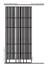
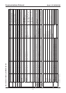
Communications Protocol
Model: VCC-MD800/700/600/500
CS: Checksum
FF: Terminator