


− 20 −
Communications Protocol
Model: VCC-MD800/700/600/500/400/300
[7] Notes
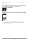
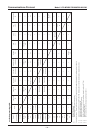
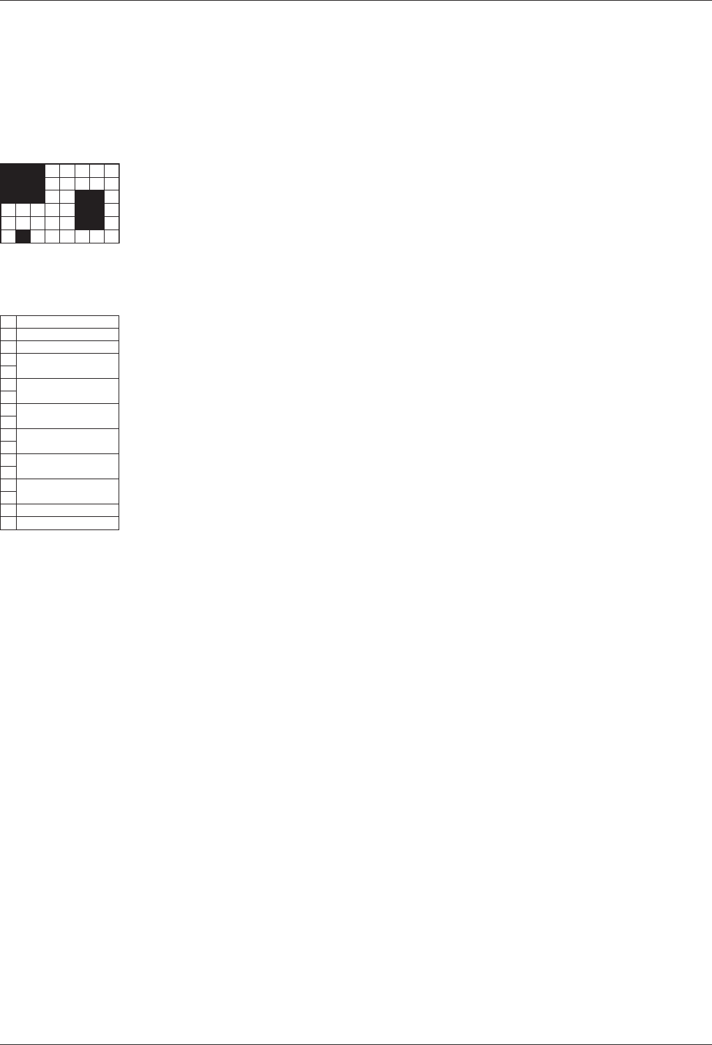
Note 1 Area Settings
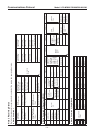
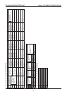
Divide the screen into 48 areas (6 vertical and 8 horizontal) and set an area to “1” to configure the mask and “0”
to not configure the mask. On a row, bits 1 to 4 from the left are on the upper level and bits 5 to 8 are on the lower
level. All six rows are connected in order from the top and transmitted according to protocol.
Example: Motion Mask Area Settings (Figure 1)
When setting Figure 1 (the area covered in black shows the position of the mask), transmit in the order described
below.
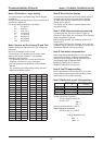
A0
08
13
07
00
07
00
07
06
00
06
00
06
02
00
CS
FF
Header
Motion Command
Motion Area Settings
First Row (00000111
0111, 0000)
Second Row (00000111
0111, 0000)
Third Row (01100111
0111, 0110)
Fourth Row (01100000
0000, 0110)
Fifth Row (01100000
0000, 0110)
Sixth Row (00000010
0010, 0000)
Checksum
Terminator
* The setting commands for the ATW Mask Area, Mask BLC Area are also transmitted using the procedure
described above.
* The Motion Detection Area (Query command Status type 8) also responds in the order described above.
(The area where motion is detected is set to “1”.)