


− 5 −
Input-Output Terminal Descriptions
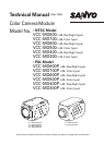
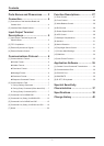
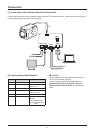
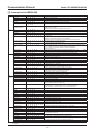
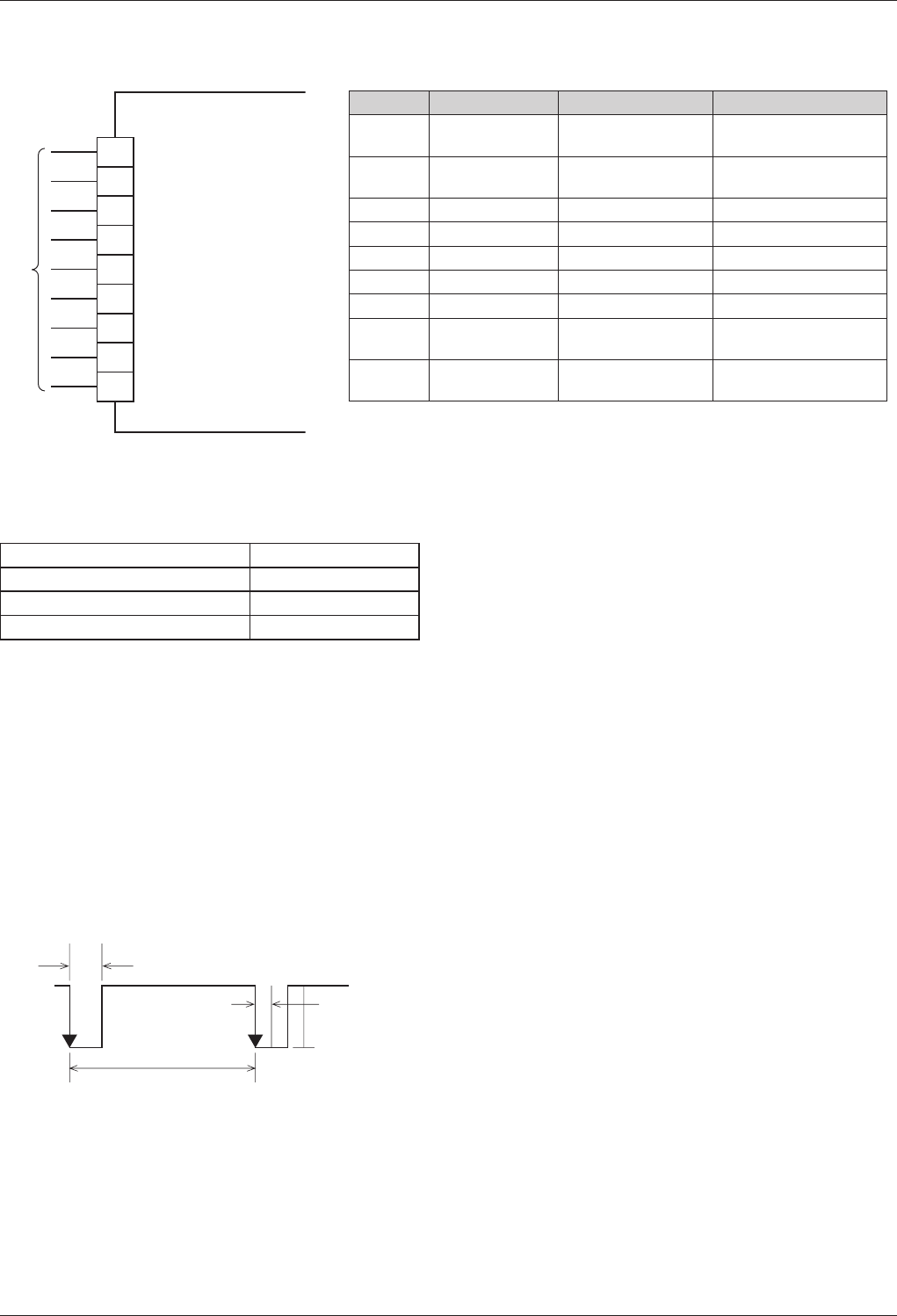
[1] Input-Output Terminal Layout and Specifications
Power Supply: DC 6-12V
1 RD
2 SD
3 GND
4 DC N (+6 – 12V)
5 GND (DC)
6 VIDEO
7 GND (VIDEO)
8 LINE IN
9 GND (LINE IN)
CAMERA
FFC
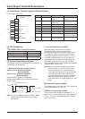
Pin Number
Signal Name Function I/O Signal Specifications
1 RD: RS-232C Communication Line
(Receiving)
Low: Max 0.8V
High: Min 2.0V
2 SD: RS-232C Communication Line
(Transmitting)
Low: Max 0.1V
High: Min 4.4V
3 RD&SD GND Communication GND —
4 DC IN
DC Power Supply Input
DC +6 – 12V
5 DC IN GND Power Supply GND —
6 VIDEO OUT 75
Ω
C Cut Output 1.0V±0.2Vp-p
7 VIDEO OUT GND Imaging GND —
8 LINE IN External Tuning Input 60 (50: PAL) Hz ±0.25
Negative Synchronization
9 LINE IN GND External
Synchronization GND
—
[2] FFC Compliance
FCI SFW9R-1STE1LF (Lead Free Product)
⁃
Core Number 9 pin
Pitch Between Conductors 1.00±0.05 mm
Length of Recommended Insulation Under 108.0±0.10 mm
Thickness of Terminal 0.30±0.05 mm
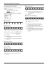
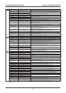
[3] External Synchronous Signals
This camera module uses external synchronization to
synchronize with the camera.
1 External Synchronization Specifications
NTSC Format: 60 Hz±0.25 (Negative
⁃
Synchronization)
PAL Format: 50 Hz±0.25 (Negative
⁃
Synchronization)
Input the LINE IN signal into the external
synchronization signal input terminal of the camera
(8 and 9 pins).
LINE IN
5V
(high: min. 4.0V)
0V
(low: max. 0.8V)
60 Hz±0.25 Hz
Pulse Width: 2m-10 ms
Shaking:
Less than 50µs
Note: Do not input signals other than LINE IN. Image
synchronization failure may occur (shaking,
jittering, etc.).
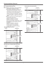
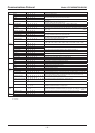
2 Internal/External Synchronization
When the power to the camera is turned on,
the external signal is input into the external
synchronization signal input terminal (8 and 9 pins).
The camera is driven by external synchronization
in the case of external synchronization (L-L). Even
if external synchronization is input, this does not
switch in the case of internal synchronization (INT).
When there is no input signal, the 8 pin is set to
Open and High:5V and is automatically set to internal
synchronization camera drive.
Note: When the camera is configured to external
synchronization (L-L), do not use the 8 pin
to fix the LowGND. This shifts the internal
synchronization frequency of the camera and
normal imaging signals cannot be emitted.
Although synchronous switching is automatic
even when switching the signal input after
turning the power on, image shaking, etc. may
occur.
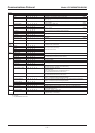
[4] External Camera Control
This camera module can control the various functions
from the RS232C port of a PC, etc.
RS232C Communications Circuit
⁃
The communication interface of the camera (1, 2,
and 3 pins) is on the C-MOS level. A level shift circuit
(5Vp-p
12Vp-p) is separately required to directly
input to a PC, etc.