


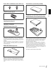

Overview
Location and Function of Parts
13
Location and Function
of Parts
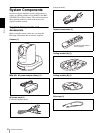
Camera
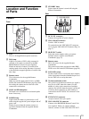
Front
A Lens
This is a 18-magnification optical zoom lens.
B Tally lamp
Lights in red when a VISCA tally command is
received or the camera is selected by the RM-
BR300 Remote Control Unit (not supplied).
Flashes at intervals of about 0.5 seconds if the
rotating speed of the cooling fan motor is lowered
or the motor has stopped regardless of on/off of the
tally lamp.
C Remote sensor
This is the sensor for the supplied Remote
Commander.
When you use the upper remote sensor, set IMG-
FLIP to ON in the SYSTEM menu (page 28). With
this setting the remote sensor at the rear of the
camera does not function.
D SONY and HD nameplates
Pull them out to turn them over and attach upside
down if necessary.
E POWER lamp
Lights when the camera is connected to an AC
outlet using the supplied AC power adaptor and AC
power cord.
Flashes in green when the camera receives an
operation command from the supplied Remote
Commander.
F STANDBY lamp
Lights when the camera is turned off using the
Remote Commander.
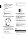
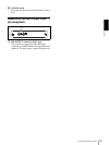
Rear
G DC IN 12V connector
Connect the supplied AC power adaptor.
H VISCA RS-422 connector
Used for VISCA control.
For connection to the VISCA RS-422 connector,
see “Using the VISCA RS-422 Connector Plug” on
page 73.
I IR SELECT switch
Select the camera number when you operate
multiple cameras with the same Remote
Commander (page 33).
J Remote sensor
This is the sensor for the supplied Remote
Commander.
This remote sensor does not function when IMG-
FLIP is set to ON in the SYSTEM menu (page 28).
K DATA MIX switch
Set the switch to ON to overlap the menu with the
video signal output from the installed Output Card.
Set it to OFF not to overlap the menu.
L 75-ohm termination switch
This switch is used when an external sync signal is
used. Set it to OFF when this camera is in the
middle of a daisy chain connection of multiple
cameras. Set it to ON when the camera is at the end
of a daisy chain connection or when nothing is
connected to the EXT SYNC IN connector on the
camera.
M EXT SYNC IN connector
Accepts external video sync signals.
N VISCA RS-232C IN connector
Connect to the RM-BR300 Remote Control Unit
(not supplied). When you connect multiple
cameras, connect it to the VISCA RS-232C OUT
1
56
32
4
RGB/COMPONENT
VISCA RS-422
123456789
EXT SYNC IN
VIDEO
IR SELECT
75
1
2
3
OFF ON
DATA MIX
OFF ON
IN VISCA RS-232C OUT
S VIDEO
!
DC IN 12V
R
qfqg qhqj
7
890qaqsqd
qk ql