


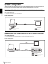
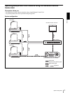
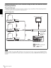

Overview
Location and Function of Parts
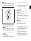
18
Blue: The power of the camera is on.
Yellow green: The camera is in standby mode.
Off: No camera is connected.
Hold down this button and press CAMERA button
1 to 7 to turn on/off the power of the camera
corresponding to the pressed button.
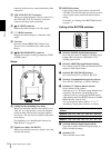
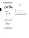
S CAMERA buttons
Press one of the buttons to select the camera from
among those connected. The selected CAMERA
button lights in blue.
T POSITION buttons
You can store the various camera settings such as
the pan, tilt and zoom positions to the memory of
the camera corresponding to each POSITION
button, and load the settings in the memory.
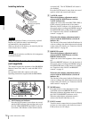
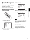
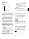
Rear/Bottom
U MODE selector
Select the position corresponding to the VISCA-
controllable camera to be connected.
Note
Set the selector to position 8 when all the connected
cameras are BRC-Z330s. For other connections, set
the selector to position 0.
V VISCA RS-232C connector
Connect to the VISCA RS-232C IN connector of
the camera.
W VISCA RS-422 connector
Connect to the VISCA RS-422 connector of the
camera.
An RS-422 connector plug is attached at the
factory.
X TALLY/CONTACT connector
This connector is used for the tally lamp input or the
contact output.
Select the function of the connector using the
TALLY/CONTACT selector.
An RS-422 connector plug is attached at the
factory.
Y TALLY/CONTACT selector
Select the function of the TALLY/CONTACT
connector.
TAL LY: The tally lamp of the camera selected
with the connected switcher lights.
CONTACT: The contact output corresponding to
the camera address selected with the Remote
Control Unit is short-circuited against the
connected switcher.
CONTACT (TALLY): The contact output
corresponding to the camera address selected with
the Remote Control Unit is short-circuited against
the connected switcher and the tally lamp of the
camera selected with the Remote Control Unit
lights.
Notes
• Change the setting of the selector before you turn
on the power for the Remote Control Unit.
Otherwise, the setting is not effective.
• For more details on the functions of the TALLY/
CONTACT selector, refer to the Operating
Instructions of the RM-BR300.
wh DC IN 12V connector
Connect the supplied AC power adaptor.
wj DIP switches (bottom)
Switch 1 (RS-232C/RS-422 selector)
Set to ON for RS-422, or OFF for RS-232C.
Switch 2 (Communication baud rate selector)
Set to ON for 38400bps, or OFF for 9600bps.
Switch 3 (BRIGHT control function selector)
Set to ON for IRIS and GAIN adjustments, or OFF
for IRIS adjustment only.
Note
Set the DIP switches before you turn on the power
of the Remote Control Unit. Otherwise, the setting
is not effective.
Switch position Camera mode
0 Automatically selected (default)
1 BRC-300/300P
2 EVI-D70/D70P
3 EVI-D100/D100P
4 EVI-D30/D30P
5SNC-RZ30N
6 BRC-H700
7 BRC-Z700
8 BRC-Z330
MODE
VISCA
1919
RS-422 ON/OFF
TALLY/CONTACT
RS-232C
CONTACT(TALLY)
!
TALLY
CONTACT DC IN 12V
w
s
w
d
w
f
w
g
w
h
w
j
w
k
w
a