


30
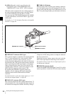
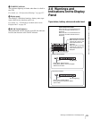
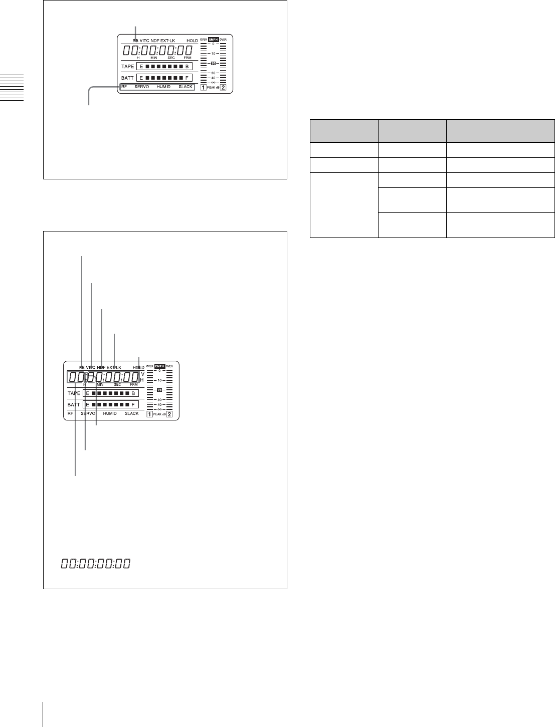
Warnings and Indications on the Display Panel
Chapter 2 Locations and Functions of Parts and Controls
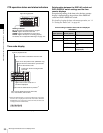
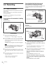
VTR operation status and status indicators
VTR operation and status indicators
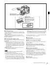
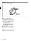
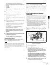
Time code display
Time code display
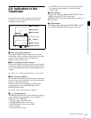
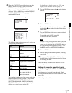
Relationships between the DISPLAY switch and
DATA DISPLAY switch settings and the time
counter displays
Except during setting of the time code, the time counter
display is determined by the position of the DISPLAY
switch and DATA DISPLAY switch.
For details of setting the time code menu operation, see “4-
5-1 Setting the Time Code” on page 64.
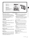
Warning indication
RF: Lights if the recording heads are clogged.
SERVO: Lights if the servo motor fails.
HUMID: Lights if condensation is on the drum.
SLACK: Lights if the tape is not winding properly.
For details, see “8-3 Operation Warnings” on page 127.
Lights during playback
Lights when the time code generator
is on hold.
Lights in playback mode.
Lights when VITC is selected for the time code.
Lights in non-drop frame mode. (DVW-970 only)
Lights when the camcorder is synchronized
with an external time code.
Lights when the time code, CTL or
real time is displayed.
1) When the HOLD button is pressed to hold the time code value,
the time code is displayed in the format shown below. When the
HOLD button is pressed again to release the hold, the time code
is displayed in the normal format.
Lights when the HOLD button is pressed.
1)
Time counter display: Shows the time code,
CTL, user bit data, and real time.
Switch settings related to time code and displayed
information
DISPLAY
switch position
DATA DISPLAY
switch position
Displayed information
CTL Any position CTL
TC Any position Time code
DATA U-BIT User bits
SHOT-TIME Data and time from shot
data
SHOT-NO Not used (currently zero
is displayed.)