


Chapter 1 Overview
Chapter 1 Overview 15
CAM/DL: This setting uses the DynaLatitude
function, which finely adjusts the contrast of each
pixel according to a histogram of luminance signal
levels. Access advanced menu page 2 to set the
DynaLatitude function ON or OFF. The
DynaLatitude effect can be set to any of three
levels, Low, STD (standard), and High with basic
menu page 2.
BARS: This setting displays color bars.
For details of menu operation, see Chapter 4 “Viewfinder
Screen Displays and Menus” (page 51).
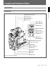
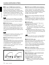
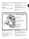
qa GAIN switch
This selects one of the three gain settings, high,
medium or low. You can choose the gain values
assigned to the H, M and L settings from values from
–3 dB to 24 dB + DPR and HYPER GAIN. (See page
64.) The factory default selections are 18 dB (H), 9 dB
(M) and 0 dB (L).
Note
When the HYPER GAIN switch ql is in the ON
position, the GAIN switch has no effect.
qs NG button
When using the ClipLink function during shooting,
you can designate a particular scene as “NG” (No
Good) by pressing this button before shooting the next
scene. Press the button again to cancel the NG setting.
qd Breaker switch
If there is a fault in the camera power supply, the
breaker trips, and the camera power supply is
disconnected. Correct the fault in the power supply,
then press this switch.
qf REC (recording) TIME switch
This selects the recording time indication in the
viewfinder.
TTL: Displays the total recording time.
The total recording time is not reset even when
you stop the VTR and power off the camera, for
example, to replace the battery pack.
DUR: Displays the recording time of the current cut.
OFF/TC: Switches off the recording time display.
If, however, a PVV-3/3P is connected, and in the
advanced menus you set the time code display
item (TC IND) to ON (see page 67), then the VTR
time data (time code, CTL count, or user bit
value) is displayed.
Note
The recording time displayed when this switch is set
to the TTL or DUR position is obtained by counting
the duration of the internal reference signal input to
the camera.
The value may not agree exactly with the value
derived from the time code values. Furthermore, the
value displayed may not be correct when another
manufacturer’s VTR is connected to the camera.
qg TTL (total) RESET button
Pressing this button resets the total recording time
(TTL selection) to zero.
qh SKIN DTL (skin detail) switch
Set this switch to ON to use the skin detail correction
function.
For details, see “Skin Detail Correction” (page 93).
qj SKIN DTL (skin detail set) SET button
Press this button with the SKIN DTL button qh to
display the area detect cursor on the viewfinder screen.
Place the cursor on the target and press this button to
perform skin detail correction.
For details, see “Skin Detail Correction” (page 93).
qk SET UP switch
Use this switch to select the camera head setup
method.
STD: Set up using the setup menu. Setup file data is
not displayed.
FILE: Set up using setup files and the setup menu.
ql HYPER GAIN switch
Setting this switch to the ON position increases the
gain by a factor of about 60 or 120 with respect to 0
dB (a 30 or 36 dB increase by electronic amplification
and a 6 dB increase for DPR, bringing about a total
gain increase of 36 or 42 dB).
When this switch is in the ON position, the indication
“HYPER” appears in the viewfinder, and the GAIN
UP indicator in the viewfinder also lights.
When finished shooting, return this switch to the OFF
position. The “HYPER” indication disappears and the
GAIN UP indicator goes out.
Note
Increasing the gain with this switch reduces the
horizontal resolution by 50%.