


Chapter 1 Overview
18 Chapter 1 Overview
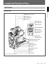
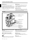
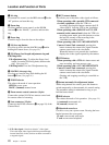
7 REMOTE connector 1 (mini-jack)
Connect the RM-LG1 Remote Control Unit to enable
remote operation of the ClipLink function.
8 MONITOR OUT connector (BNC)
Outputs both the camera video and the character
information as displayed on the viewfinder screen.
You can connect an optional LCD color monitor to this
connector.
9 VIDEO OUT connector (BNC)
This outputs the video signal captured by the camera.
0 REMOTE connector 2 (10-pin)
Connect the optional RM-M7G Remote Control Unit
to this connector. Set the CAMERA HEAD SELECT
switch on the bottom of RM-M7G to 1.
Note
When using the RM-M7G, note the following points.
• When operating the camera head from the camera
control unit, connect the RM-M7G to the camera
control unit.
• EZ mode cannot be used if the RM-M7G is
connected to the camera head.
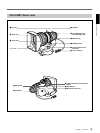
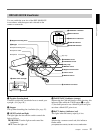
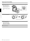
Location and Function of Parts
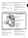
qa LENS connector (12-pin, for
2
/3-inch lens)
Connect the lens connector.
qs VF (viewfinder) connector (8-pin)
This is the connector for the DXF-41/51 viewfinder.
Note
When using this connector, do not connect a DXF-801/
801CE viewfinder to the VF connector on the front of
the camera head.
qd VTR connectors (PRO 76-pin DIGITAL and
PRO 50-pin)
Connect a dockable VTR. A PRO 76-pin DIGITAL
connector is for the DSR-1/1P and a PRO 50-pin
connector is for the PVV-3/3P or a camera adaptor.