


2-6 (E)
HDCU-900 MM
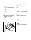
2-6. Replacing the RX-53 Board
m
. The electric parts mounted on the RX-53 board cannot
be replaced or adjusted.
If the electric parts need to be replaced or adjusted,
replace the entire unit.
. If you bend or pull out the optical fiber cable forcibly,
disconnection may result. Handle the cable carefully.
Replacement Procedure
1. Turn off the main power and disconnect the plug from
the outlet.
n
Wait for at least three minutes before starting replace-
ment, because there are electrically live blocks inside
the machine that could cause electric shock.
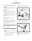
2. Remove the rear panel. (Refer to Section 2-3.)
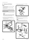
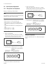
3. Remove the three screws and slide the optical unit in
the direction of the arrow.
4. Disconnect the connectors (CN26, CN29) of the MB-
902 board and remove the optical unit.
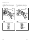
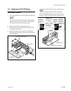
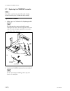
2-6. Replacing the RX-53 Board
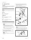
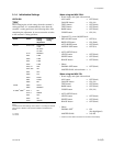
5. Remove the four screws and remove the CAMERA
connector from the optical unit.
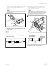
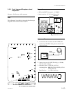
6. Disconnect the two connectors from the rod holder.
(Fig. 1)
7. Rotate each knurl block in the direction of arrow A to
remove the connector. (Fig. 2)
n
The interconnection connector should be remain
connected to the mate connector (yellow). To avoid
the signal degration, do not touch an exposed tip of the
connector.
B3 x 5
B3 x 5
CN26
CN29
MB-902 board
Optical unit
A
Connectors
Interconnection
connector
Light
blue
Yellow
Cream color
Rod holders
Fig.1
Fig.2
Knurl block
Optical unit
B3 x 5
B3 x 5
CAMERA connector