


3-11 (E)
HDCU-900 MM
3-4. Video Signal System Adjustment
(RC-86 Board)
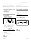
3-4-1. SD-SDI Output VCO Adjustment
Measure : Frequency counter
Note
After replacing IC508 or IC510 on the RC-86 board only,
perform this adjustment.
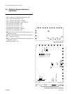
Preparation
. Board extension : RC-86 board (front side)
. COR501 (B-8)/RC-86 → FREE RUN (Short between 2-
pin and 3-pin.)
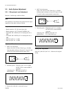
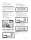
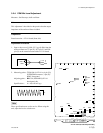
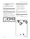
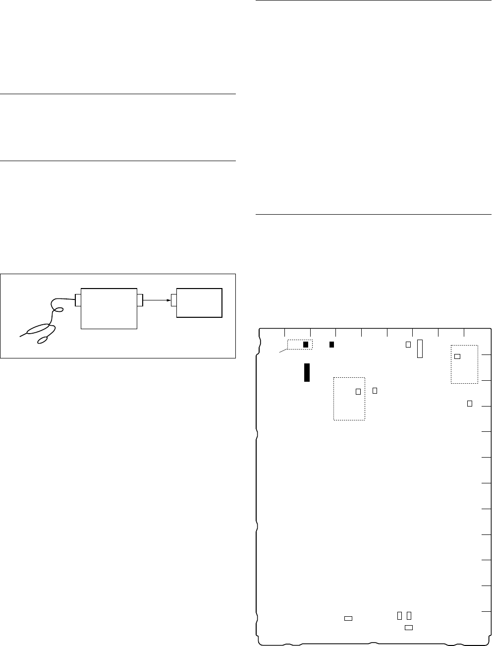
. Connect the measure as shown in the following figure.
. After turning on the power, wait for 10 minutes at least
and start adjustment.
Probe
Oscilloscope
Frequency
counter
CH2
IN
CH2
OUT
IN
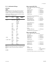
Adjustment Procedure
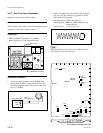
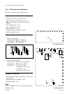
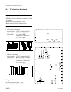
1. Measuring point : TP501 (A-7)/RC-86
Adjusting point : 1RV501 (A-7)/RC-86
Specifications : 27.0 ±0.2 MHz
2. Measuring point : TP502 (A-8)/RC-86
Adjusting point : 1RV502 (A-8)/RC-86
Specifications : 27.0 ±0.2 MHz
Note
After finishing the adjustment and waiting for 10 minutes
at least, confirm that each specification is satisfied.
If the specifications are not satisfied, perform the adjust-
ment again.
Setting after Adjustment
COR501 (B-8)/RC-86 → NORMAL
(Short between 1-pin and 2-pin.)
A
B
C
D
E
F
G
H
J
K
L
M
123456789
S803
S801
S802
S811
11
RV353
RV350
RV352
1
TP603
TP352
RV601
COR601
TP350
1
TP501
RV501
1
TP502
RV502
COR501
1
TP201
RV201
TP703
RV701
Suffix:14_
Suffix:14_
1
1
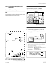
RC-86 board (A side)
3-4. Video Signal System Adjustment (RC-86 Board)