3-1 (E)
HDCU-900 MM
Section 3
Electrical Alignment
3-1-2. Notes on Adjustments
. The measure should have already been calibrated.
. “3-1-4. Initialization Settings” have already been
finished.
. The adjustment of the HDC-900 (or HDC-950) haven
already been finished.
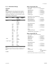
. Types of the color bars to be output from the built-in SG:
Signal format Y C
HD-SDI 100 % 100 %
HD-Analog 100 % 100 %
SD-SDI (D1) 100 % 75 %
*1
SD-Component-analog 100 % 75 %
*1
(HKCU-901)
SD-Composite-analog 75 % 75 % (SMPTE)
(HKCU-901)
SD-Composite-analog 100 % 75 % (EBU)
(HKCU-901)
*1 : When S811-1 on the RC-86 board is ON and S811-2 is OFF (factory
setting)
. To adjust the unit, extend each plug-in board. Before
pulling out the boards, be sure to turn off the main
power.
. Before starting adjustment, warm up for about 10
minutes.
. Before using the MSU-700A/750, check the version of
the ROM. For details, refer to Section 1-1, “Checking
the ROM Version” of the separate Installation and
Maintenance Manual.
3-1. Preparation
3-1-1. Required Equipment
Measures
. Digital oscilloscope (300 MHz or higher)
Tektronix TDS460A or equivalent
. HD waveform monitor
Tektronix 1735HD/1730HD or equivalent
. SD waveform/Vector monitor
Tektronix 1780R or equivalent (for UC)
Tektronix 1781R or equivalent (for CE)
. SD signal generator
Tektronix TSG170A or equivalent (for UC)
Tektronix TSG271 or equivalent (for CE)
. Audio oscillator
Tektronix SG-5010 or equivalent
. Frequency counter
Advantest TR5821AK or equivalent
Related equipment
. HDVS color video camera
HDC-900 (or HDC-950)
. Master setup unit
MSU-700A/750
Tools
. Front extension board BKP-7900
. Rear extension board EX-525A
(Sony P/N : A-8326-353-A)
. Extension board EX-738 (for HDC-900/950)
(Sony P/N : A-8327-351-A)


