


9
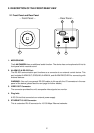
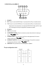
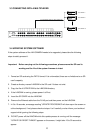
2.2 RS-232 Port & ALARM I/O
1 2 3 4 5
9876
1. RS-485 D-
2. RX: This pin is one of the RS-232 pins. It connects with the TX pin of another device.
3. TX: This pin is one of the RS-232 pins. It connects with the RX pin of another device.
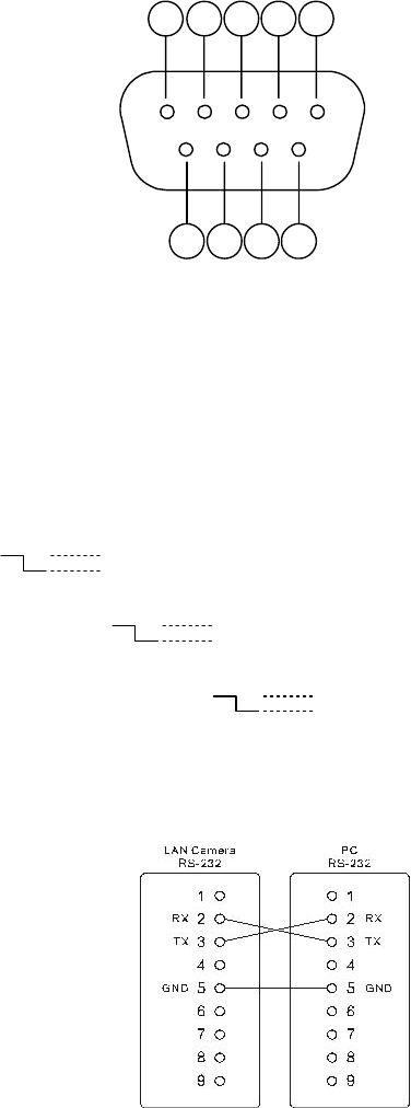
Please refer to the note below on the standard RS-232 9 Pin Cable with Pin 2 and
Pin 3 exchanged; see the pin configuration chart below for details.
4. RS-485 D+
5. GND: Ground contact.
6. ALARM RESET (INPUT): This pin connects to an alarm-clear device for clearing an
alarm. (
5V, 20mA
0V(Active)
)
7. ALARM IN (INPUT): This is an alarm input that can be programmed in the menu
system to active low. (
5V, 20mA
0V(Active)
)
8. ALARM OUT (OUTPUT): This is an alarm output trigger. Connect this to external
devices such as buzzers or lights. (
5V, 20mA
0V(Active)
)
9. AUDIO OUT: This provides the unit’s audio signal to a speaker.
The pin configuration chart: