


10
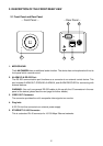
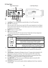
2.3 Flank Panel
-- Right Flank Panel -- -- Left Flank Panel --
1. Lens Mount: This LAN CAMERA is used with either a C or a CS mount lens.
2. ALC VR: Iris control VR.
When an auto iris (DC Drive) lens is used, this VR is used to adjust the iris for different
lighting environments. Adjust the VR clock-wise to open the iris and counter-clockwise
to close the iris of the camera.
3. RESET: Recover to factory default.
4. IRIS: Auto iris connector.
This camera works with a DC drive auto iris lens. Please refer to the pin assignment
marked on the camera when connecting the auto iris lens.
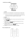
5. DIP Switch:
1. AES: Auto electric shutter.
2. DC IRIS: Use an auto iris (DC drive)
3. DHCP: Turn On / Turn Off to use the DHCP protocol. If the switch
points upwards, the device can change the setup of
network function (enable/disable) via the network.
4. STATIC IP: If the switch points down, the device can’t obtain an IP
address from the DHCP server. This option is needed
to configure the network communication settings.
6. POWER Indicator: Indicates the power status of the unit. The green light indicates the
unit is activating. The red light indicates the power is on and the SD card cannot be
removed.
7. LAN Indicator: Indicates the LAN status of the unit. The green light indicates the 100
Mbps Ethernet network is activating. The red light signals the LAN is data linking.
8. RS-485 Port: The RS-485 communication ports function as connectors when two or
more units are serially connected to an external control device.
9. 5pin MINI USB Port: The user can use a USB device cable to connect the LAN
CAMERA to the USB port on the PC.
10. SD CARD Slot: This is used for system software updating and archiving / accessing
critical images