


Locations and Functions of Parts and Controls
24
Chapter 1 Overview
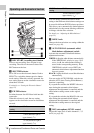
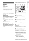
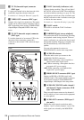
j TC IN (timecode input) connector
(BNC type)
To apply an external lock to the timecode of the
camcorder, input the reference timecode.
For details, see “Setting the Timecode” (page 62).
k VIDEO OUT connector (BNC type)
Outputs video signals for monitoring. The output
signals can be selected either composite video or
HD-Y depending on the setting of OPERATION
>Input/Output >Output&i.LINK in the setup
menu.
l TC OUT (timecode output) connector
(BNC type)
To lock the timecode of an external VTR to the
timecode of this camcorder, connect this
connector to the external VTR’s timecode input
connector.
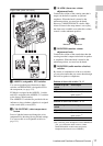
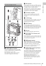
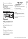
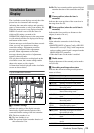
Rear
a TALLY (back tally) indicators (red)
Light up during recording. They will not light if
the TALLY switch is set to OFF. These indicators
also flash to indicate warnings (see page 20). The
tally indicator on the front of the viewfinder and
the REC indication on the viewfinder screen light
or flash in the same manner.
For details, see “Operation Warnings” (page 148).
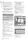
b TALLY switch
Set to ON to activate the TALLY indicator
function.
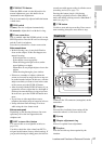
c EARPHONE jack (stereo, minijack)
You can monitor the E-E sound during recording
and playback sound during playback. When an
alarm is indicated, you can hear the alarm sound
through the earphone. Plugging an earphone into
the jack automatically cuts off the built-in
speaker.
You can select monaural or stereo on
MAINTENANCE >Audio in the setup menu.
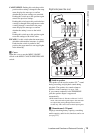
d AUDIO IN selectors
Select the audio source you connect to the
AUDIO IN CH1/CH2 connectors.
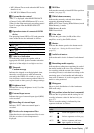
LINE: When connecting a stereo amplifier or
other external audio signal source
MIC: When connecting a microphone that does
not require 48 V power supply
+48V: When connecting a microphone that
requires 48 V power supply
e HD/SD SDI OUT connector (BNC type)
Outputs an HD SDI or SD SDI signal (with
embedded audio). The output from this connector
can be turned on and off with OPERATION
>Input/Output >SDI Output in the setup menu.
f AUDIO IN CH1/CH2 (audio channel 1
and channel 2 input) connectors (XLR
type, 3-pin, female)
These are audio input connectors for channels 1
and 2 to which you can connect audio equipment
or a microphone.
g AUDIO OUT connector (XLR type, 5-
pin, male)
Outputs the audio signals recorded on audio
channels 1 and 2 or audio channels 3 and 4. The
audio signals are selected by the MONITOR
switch.