


Locations and Functions of Parts and Controls
25
Chapter 1 Overview
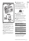
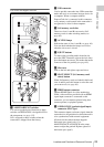
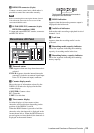
h REMOTE connector (8-pin)
Connect a remote control unit, which makes it
possible to control the camcorder remotely.
Note
Before connecting/disconnecting the Remote Control
Unit to/from the camcorder, be sure to turn off the
camcorder POWER switch.
i i.LINK (HDV/DV) connector (6-pin,
IEEE1394 compliant, S400)
To input and output HDV/DV streams, connect to
an HDV/DV device.
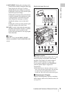
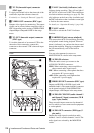
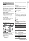
a Timecode status
NDF: Appears when non-drop-frame timecode is
selected.
EXT-LK: Appears when the internal timecode
generator is locked to an external signal input
to the TC IN (timecode input) connector.
b Counter display mode
Shows the type of information selected by the
DISPLAY switch to be displayed in the time
counter display.
COUNTER: Counter values
TC: Timecode
U-BIT: User bits data
c Time counter display
Switches displays of time counter values,
timecode, and user bits data, depending on the
position of the DISPLAY switch.
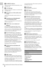
When the HOLD button is pressed to hold the
timecode value, the timecode is displayed in the
format shown below. When the HOLD button is
pressed again to release the hold, the timecode is
displayed in the normal format.
d HOLD indication
Appears when the timecode generator output is
displayed in the hold mode.
e Audio level indicators
Indicate the audio recording or playback levels of
channels 1 to 4.
f Lock icon
Appears when the recording media is write-
protected.
g Remaining media capacity indicator
Shows bar segments indicating the remaining
capacity of recording media in the slots.
h Remaining battery capacity indicator
Shows bar segments indicating the remaining
battery capacity.
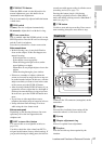
Monochrome LCD Panel
The three dots indicates that timecode is
displayed in the hold mode.