


GB
8 Location and Functions of Parts and Controls
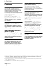
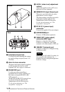
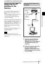
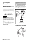
9 Installation/tripod hole
Use this hole when attaching the camera
to a wall, ceiling or tripod (screw: 1/4”,
20 UNC)
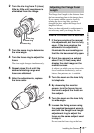
q; Auto iris lens connector
The power and control signal is supplied
to the lens when the lens iris cable
(optional, DC servo type) is connected.
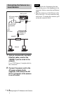
qa RS485/232C port
Use this port when controlling a
peripheral device from a computer via
the camera, using the RS-485 or RS-
232C protocols.
The RS-485 and RS-232C protocols can
be selected using the menu for the
Administrator on the Web browser.
For the pin assignment, see “Pin
assignment” on page 22.
qs LEVEL (video level) adjustment
volume
Adjust the signal level for a DC servo-
type auto iris lens (optional).
qd SENSOR I/O (Input/Output) port
This port is provided with one sensor
input and two sensor outputs.
The alarm settings using this port can be
performed using the menu for the
Administrator on the Web browser.
For the pin assignment, see “Pin
assignment” on page 22.
qf DC IN 12 V (power input)
connector
Connect the supplied AC power adaptor.
qg USB MODEM port
Connect a USB modem (optional).
qh VIDEO OUT (video output)
connector (BNC type)
Outputs a composite video signal.
Connect to a composite video input
connector of a video monitor, VCR, etc.
qj 10BASE-T (network) port
Connect to a network or computer using
an Ethernet cable.
When using a LAN cable: For safety, do
not connect to the connector for
peripheral device wiring that might have
excessive voltage.
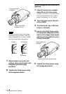
9q
;
Bottom
q
a
q
s
q
d
qf qg qh qj
Rear
Caution