


Miscellaneous
36
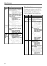
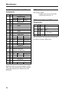
Parallel Interface Connector Pin
Assignments
USB Interface
Data transfer method
Complies with Universal Serial Bus
Specification Revision 1.0
USB Interface Connector Pin
Assignments
Pin No.
I/O Signal
Interface mode
Compatible
Nibble ECP
1 I nStrobe HostClk HostClk
2 I/O Data1 (LSB)
3 I/O Data2
4 I/O Data3
5 I/O Data4
6 I/O Data5
7 I/O Data6
8 I/O Data7
9 I/O Data8 (MSB)
10 O nACK PtrClk PeriphClk
11 O Busy PtrBusy PeriphAck
12 O PError
AckDataReq nAckReverse
13 O Select Xflag Xflag
14 I nAutoFd HostBusy HostAck
15 Not defined
16-17 GND
18 O Peripheral Logic High
(pull up to +5V with 1k Ω)
19-30 GND
31 I nInit nInit
nReverseRequest
32 O nFault nDataAvail
nPeriphRequest
33 Not defined
34 Not defined
35 Not defined
36 I
nSelectln
IEEE 1284 Active
IEEE 1284 Active
Pin No.
I/O Signal Function
VCC Cable power, maximum
current
I/O -Data Data
I/O +Data Data, pull up to +3.3V by
a 1.5 Ω resistor
Ground Cable ground
Within the bi-directional parallel interface (IEEE
STD 1284-1994) standard, the UP-DP10 supports
Compatible mode, Reverse Nibble mode, and
ECP mode.
The specifications and appearance of this printer
are subject to change without notice.