


Chapter 3: System Interface
3-1
Chapter 3
System Interface
3-1 Overview
There are several LEDs on the control panel to keep you constantly informed of the
overall status of the system as well as the activity and health of specifi c components.
There are also two buttons on the control panel. This chapter explains the meanings
of all LED indicators and the appropriate response you may need to take.
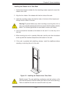
3-2 Control Panel Buttons
There are two push buttons located on the front of the chassis: a reset button and
a power on/off button.
Reset Button
The reset button reboots the system.
Power
This is the main power button, which is used to apply or turn off the main system
power. Turning off system power with this button removes the main power but keeps
standby power supplied to the system. If you need to service the system you should
unplug the AC power cord after shutting down the server.
3-3 Control Panel LEDs
The control panel located on the front of the chassis has fi ve LEDs. These LEDs
provide you with critical information related to different parts of the system. This
section explains what each LED indicates when illuminated and any corrective ac-
tion you may need to take.