


Chapter 5: Advanced Motherboard Setup
5-9
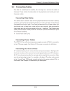
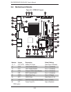
Note: Jumpers not indicated are for test purposes only.
Number Connector Description
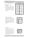
1 KB/Mouse PS/2 Keyboard/Mouse
2, 3 USB1/2 Back Panel USB Ports
4 COM1 Back Panel Serial Port
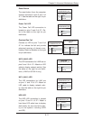
5 VGA
Video/Graphics Port
6 LAN1 RJ45 Connector for LAN1
7 LAN2 RJ45 Connector for LAN2
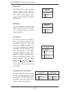
15 JL1 Chassis Intrusion Header
18 JBAT1 Onboard Battery
19 JPCIE1 PCI-E 1.1 x4 Gen1 (in x16 physical) Slot
20, 21, 23 USB 5/6, 7/8, 9 Front Panel USB Headers
22 USB 10 Type A USB Port
25 JOH Overheat Warning LED Header
26 J8 Power Connector for Add-on Devices
27 SATA 0,1,2,3,4,5 SATA Ports
29 JWF1 SATA Disk on Module (DOM) Power
30 T-SGPIO-0/1 Serial General Purpose IO Headers (for SATA)
31 JF1 FP Control Panel Header
32 JD1 External Buzzer/Speaker/Power LED
33 JPI2C PWR supply (I
2
C) System Management Bus
34 JPW1 ATX 24-Pin Power Connector
36 JSMB1 System Management Bus header
37, 38 Fans 1, 2 Fan 1: CPU Fan, Fan 2: Chassis Fan Header
39 COM2 Serial Port 2 Header
45 SPK Onboard Speaker/Buzzer
50 DIMM 1, DIMM 2 SO-DIMM Memory Slots
Note: Missing numbers are for connectors that are included on a different board
sku.