


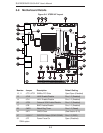

Chapter 5: Advanced Motherboard Setup
5-11
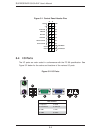
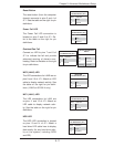
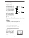
Reset Button
The reset button (from the computer
chassis) connects to pins 3 and 4 of
JF1. See the table on the right for pin
defi nitions.
Reset Button
Pin Defi nitions (JF1)
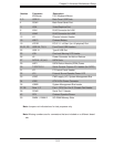
Pin# Defi nition
3 Reset
4 Ground
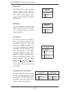
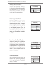
Power Fail LED
The Power Fail LED connection is
located on pins 5 and 6 of JF1. Re-
fer to the table on the right for pin
defi nitions.
PWR Fail LED
Pin Defi nitions (JF1)
Pin# Defi nition
5 Vcc
6 Ground
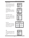
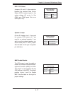
Overheat/Fan Fail
Connect an LED to pins 7 and 8 of
JF1 to indicate fan fail and provide
advanced warning of chassis over-
heating. Refer to the table on the right
for pin defi nitions.
OH/Fan Fail LED
Pin Defi nitions (JF1)
Pin# Defi nition
7 Vcc
8 Ground
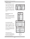
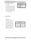
NIC2 LED
Pin Defi nitions (JF1)
Pin# Defi nition
9 Vcc
10 Ground
NIC2 (LAN2) LED
The LED connections for LAN2 are on
pins 9 and 10 of JF1. Attach an LED
cable to display network activity. See
the table on the right for pin defi ni-
tions. (LAN2 on 5015A-H only.)
NIC1 LED
Pin Defi nitions (JF1)
Pin# Defi nition
11 Vcc
12 Ground
NIC1 (LAN1) LED
The LED connections for LAN1 are
on pins 11 and 12 of JF1. Attach an
LED cable to display network activ-
ity. See the table on the right for pin
defi nitions.
OH/Fan Fail Indicator
Status
State Defi nition
Off Normal
On Overheat
Flashing Fan Fail
HDD LED
The HDD LED connection is located
on pins 13 and 14 of JF1. Attach a
hard drive LED cable here to display
disk activity (for any hard drive activ-
ity on the system, including SATA
and IDE).
HDD LED
Pin Defi nitions (JF1)
Pin# Defi nition
13 +3.3V
14 HD Active