


5-10
SUPERSERVER 5015A-EHF User's Manual
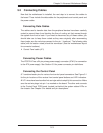
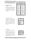
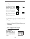
Power Button
The Power Button connection is
located on pins 1 and 2 of JF1.
Momentarily contacting both pins
will power on/off the system. To turn
off the power when set to suspend
mode, press the button for at least
4 seconds. Refer to the table on the
right for pin defi nitions.
5-9 Connector Defi nitions
Required Connection
Optional Connection
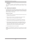
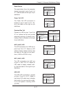
ATX Power 24-pin Connector
Pin Defi nitions
Pin# Defi nition Pin # Defi nition
13 +3.3V 1 +3.3V
14 -12V 2 +3.3V
15 COM 3 COM
16 PS_ON 4 +5V
17 COM 5 COM
18 COM 6 +5V
19 COM 7 COM
20 Res (NC) 8 PWR_OK
21 +5V 9 5VSB
22 +5V 10 +12V
23 +5V 11 +12V
24 COM 12 +3.3V
Power Button
Pin Defi nitions (JF1)
Pin# Defi nition
1 Power Signal
2 Ground
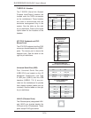
Main ATX Power Supply
Connector
The 24-pin main power connector
(JPW1) is used to provide power to
the motherboard. This power connec-
tor meets the SSI EPS 12V specifi ca-
tion. See the table on the right for pin
defi nitions.
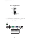
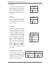
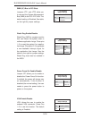
External Power Connector
In addition to the 24-pin main power
connector, the 4-pin External Power
connector at J8 is used to provide
power to external devices such as
hard disks & CD-ROM drives. This
power connector supports 12V and
5V devices.
4-Pin External Power
Connector
Pin Defi nitions
Pin Defi nition
1 +12V
2 Ground 1
3 Ground 2
4 +5V