


Chapter 5: Advanced Motherboard Setup
5-13
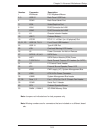
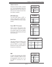
Chassis Intrusion
A Chassis Intrusion header is located
at JL1 on the motherboard. Attach the
appropriate cable from the chassis to
inform you of a chassis intrusion when
the chassis is opened.
Chassis Intrusion
Pin Defi nitions
Pin# Defi nition
1 Intrusion Input
2 Ground
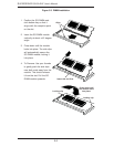
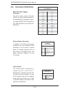
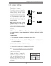
SATA DOM Power
The SATA DOM Power on JWF1 is
used to supply power to SATA Disk-
on-Module (DOM) solid-state storage
devices.
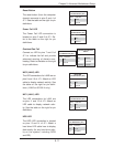
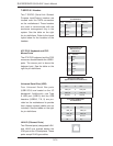
Power SMB I
2
C Connector
Power System Management Bus
(I
2
C) Connector monitors the status
of the power supply, fan and system
temperature. See the table on the right
for pin defi nitions.
PWR Supply I
2
C
Pin Defi nitions
Pin# Defi nition
1 Clock
2 Data
3 PWR Fail
4 Ground
5 +3.3V
SATA DOM Power
Pin Defi nitions
Pin# Defi nition
1 VCC
2 Ground
3 Ground
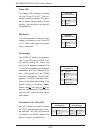
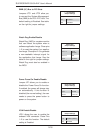
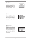
Serial Ports
Two serial ports are included on the
motherboard. COM1 is a backpanel
port and COM2 is a header located
behind the I/O ports. See the table on
the right for pin defi nitions.
Serial Port Pin Defi nitions
(COM1/COM2)
Pin # Defi nition Pin # Defi nition
1 DCD 6 DSR
2 RXD 7 RTS
3 TXD 8 CTS
4 DTR 9 RI
5 Ground 10 NC
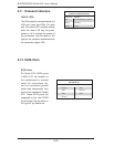
SMB
A System Management Bus (SMB)
header is located at JSMB. Connect
the appropriate cable here to use
the SMB I
2
C connection on your
system.
SMB Header
Pin Defi nition
Pin# Defi nition
1 Data
2 Ground
3 Clock
4 No Connection