


5-12
SUPERSERVER 5015A-EHF User's Manual
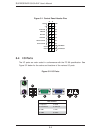
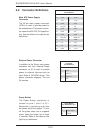
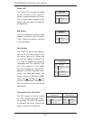
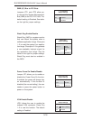
Fan Headers
The X7SPE-HF has two fan headers.
Fan1 is the CPU fan and Fan2 is for
the system cooling fan. These fans
are 4-pin fan headers. However, Pins
1~3 of the fan headers are backward
compatible with the traditional 3-pin
fans. (The speeds of 4-pin (PWM)
fans are controlled by Thermal Man-
agement via BIOS Hardware Moni-
toring in the Advanced Setting. (The
default setting is Disabled.) Note:
Please use all 3-pin fans or all 4-pin
fans on a motherboard. Please do not
use 3-pin fans and 4-pin fans on the
same board.
Fan Header
Pin Defi nitions
Pin# Defi nition
1 Ground
2 +12V
3 Tachometer
4 PWM Control
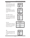
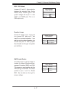
Power LED
The Power LED connector is located
on pins 15 and 16 of JF1. This con-
nection is used to provide LED indica-
tion of power being supplied to the
system. See the table on the right for
pin defi nitions.
Power LED
Pin Defi nitions (JF1)
Pin# Defi nition
15 5V Stby
16 Control
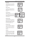
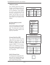
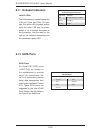
NMI Button
The non-maskable interrupt button
header is located on pins 19 and 20
of JF1. Refer to the table on the right
for pin defi nitions.
NMI Button
Pin Defi nitions (JF1)
Pin# Defi nition
1 Signal
2 Ground
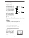
Overheat/Fan Fail LED (JOH)
The JOH header is used to connect
an LED to provide warnings of chas-
sis overheat. This LED will also blink
to indicate a fan failure. Refer to the
table on right for pin defi nitions.
Overheat LED
Pin Defi nitions
Pin# Defi nition
1 5vDC
2 OH Active
OH/Fan Fail LED
Status Message
State Message
Solid Overheat
Blinking Fan Fail